18
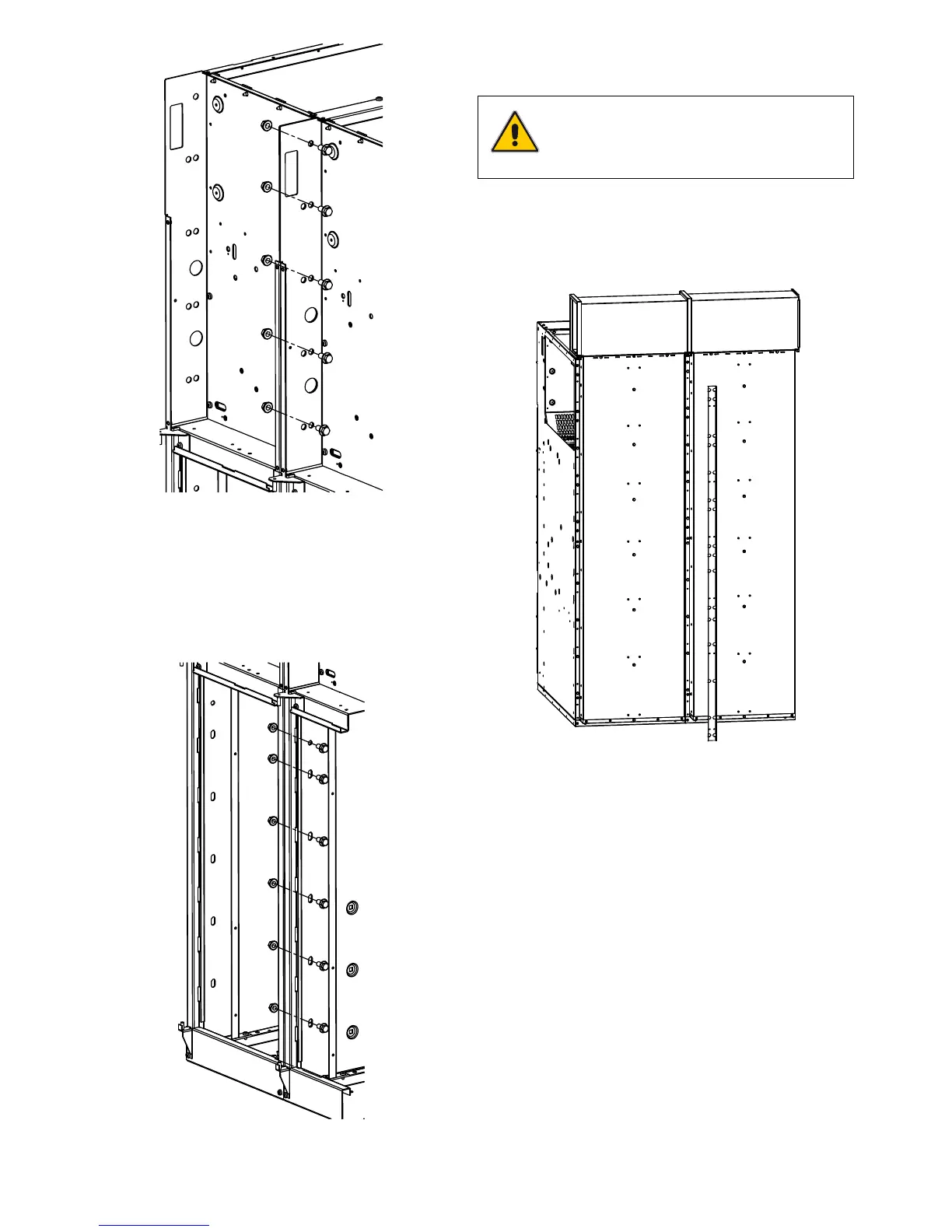
Figure 49. Screw positions for WBC – WBS units
4.5.4 Assembling the remaining switchgear units
After connecting two units, bring the third unit to the place of
installation. Then repeat the following operations:
a) Removing the roof plates
b) Connecting the units
c) Repeat the same operations for the remaining units.
Figure 47. Places for screws
g) Insert 8 bolts (M10x20 hexagonal with flange) and 8 nuts
(M10x20 hexagonal with flange) into the cable compartment
(front, lower part of the units), but do not tighten them yet.
Figure 48. Screw positions
h) Use a screwdriver to trim the unit alignment. Tighten all the
bolts from the front.
NOTE
Do not remove the roof frame for SBR
functional units.
i) For WBC and WBS units, insert 6 hexagonal bolts with the
relative nuts.