32
4. Floor plates and cable guide splines
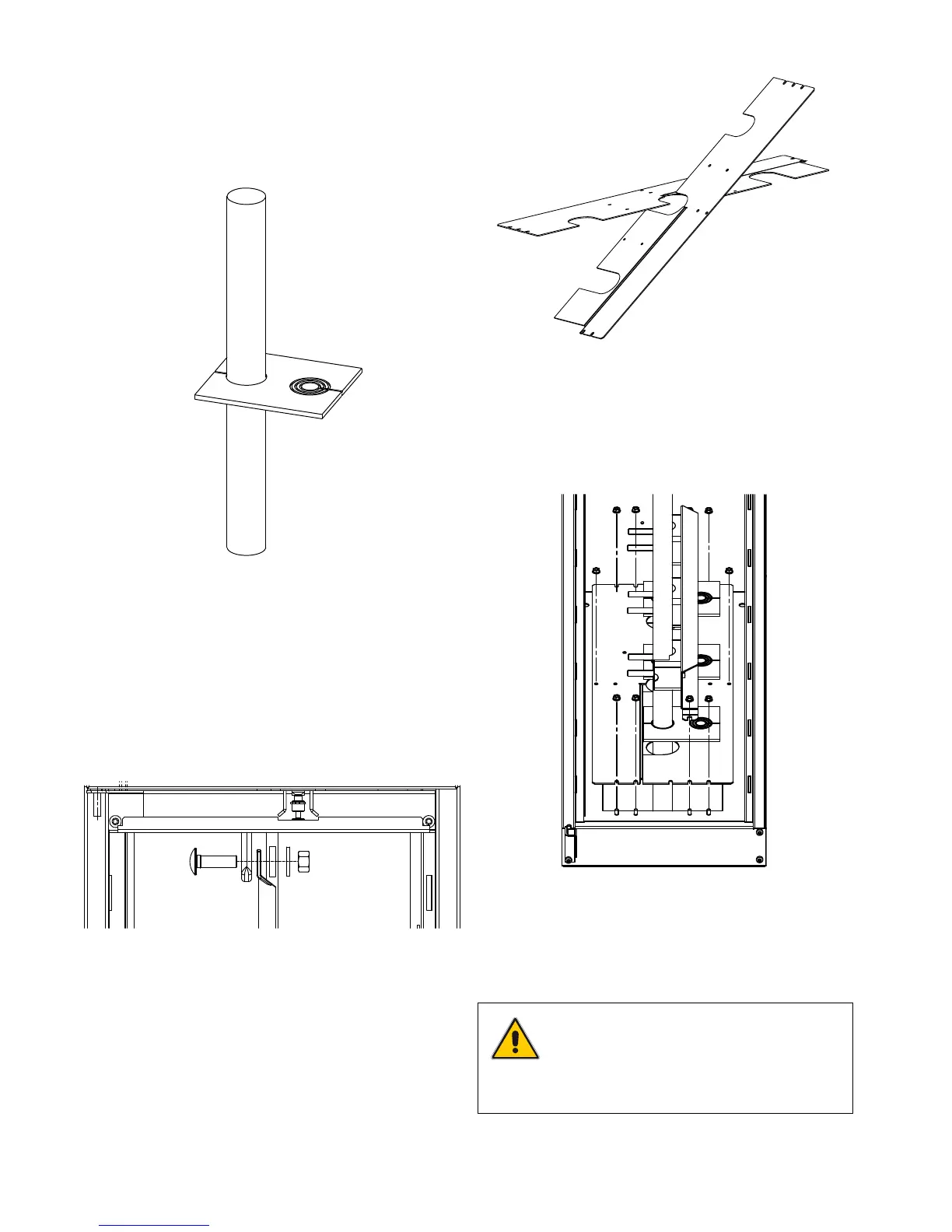
Figure 105. Floor plates
a) Insert the floor plates, fairleads, cable clamps and cable
guide splines, together with 8 nuts, on the floor of the unit
as shown in Figure 106.
NOTE
In the case of a circuit-breaker, fit the floor
plates as far apart from each other as pos-
sible so that the cables can be fitted directly
to as vertical a position as possible.
2. Cables
a) Pull the cables through the open bottom into the unit.
Measure and cut the cables to sufficient length, taking into
consideration the installation of the cable terminations and
cable terminals.
b) Adapt the fairleads to the cable diameter and fit them onto
the cable.
Figure 103. Cables and reducer rings
c) Prepare the cable insulating ends and mount them on the
cable cores according to the manufacturer’s instructions.
d) Connect the cables to the cable terminals as shown in
Figure 104.
In a switch-fuse combination, the maximum terminal width is
30 mm.
Figure 104. Connecting the cables
3. Cable clamps
a) Remove 2 nuts (per phase) from the left hand side of the
cable clamps.
b) Remove the loose sides of the cable clamps.
Figure 106. Installation of the floor plates,
cable guide splines, cable clamps and fairleads
b) Screw up all eight nuts.