XIO USER MANUAL | 2106424MNAB | 197
be used for field network connections. Connections on A1 and A2 are part of the same logical network.
One port (A2 for example) can be used to connect other field devices in daisy-chained configuration.
The other port (A1) can be left available for local connection by an operator or field technician (see
connection for laptop 4 in the figure). Connection to A1 gives access to all the devices, provided that the
operator laptop is configured with a compatible IP address.
With this configuration, if the other devices are not collocated with the XIO, operators do not have to
move to the location of the other devices to access them. Access is available from the A1 port. In this
scenario, either interface B1 or B2 can be selected as the enterprise or uplink interface to the corporate
WAN (2). Local access to all devices associated with the A1+A2 Network is also available on any unused
port on those devices (See laptop 4 connecting to A1 on the port forwarding XIO and laptop 5 connecting
to port B2 on the XIO-1).
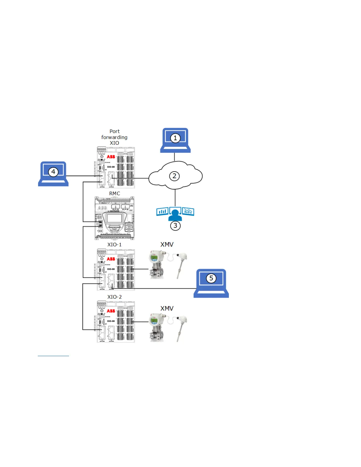
Figure 9-13: Use A-Network ports for field LAN connections
Figure 9-14
shows a logical diagram of the networks associated with the B1 interface (network 3) and the
A1+A2 interface (network 5). The operator can connect to the port forwarding XIO on port A1 (see laptop
4) and be able access all field devices on that logical network (5). The RMC, XIO-1, and XIO-2 are
configured in 2- and 4-port switch modes. All their Ethernet interfaces are associated with network 5.
 Loading...