19
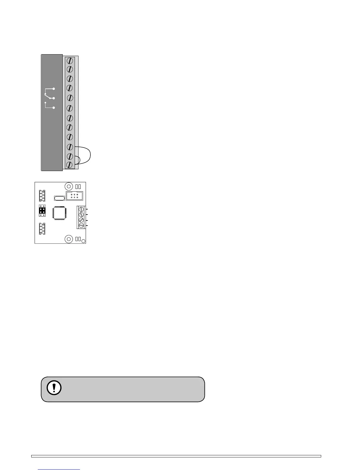
EXTERNAL CONNECTIONS
12345678910
11 12
+24V out
GND
Normal
Not
y
Lockin
g
GND
circuit
t
in use
r
impulse
Fire
detector
+12V out
Delayed
impulse
12 +24 VDC, 500 mA output
11 +12 VDC, 1,0 A output
10 Ground
7, 8, 9 Potential free relay output for lock drive
6 Normal impulse
5 Delayed impulse. Door will open after 1,0 seconds delay
4 Not in use
3 Locking circuit (Inhibits the opening if the lock bolt is out.
Grounding this input allows the opening)
2 Fire detector
1 Ground
Fire detector
Take connection loop between 1 and 2 away if fi re detector is connected. Connect fi re detector between 1 and 2
and check fi re jumper (fi re n.c.). After fi re alarm, one manual opening is required to re-energise the operator to
chosen program selector mode.
Safety Sensor
The Safety Sensor is connected to terminals 1 and 4. More information on page 21. Safetysensor safetyimpulse
outputs (white and violet) are equipped with normally closed (NC) relays. Choose jumpers J2 (opening side) and
J3 (Closing side) on to switch on safety sensor monitoring.
1
2
3
4
J1
J2
J3
J4
1 Monitoring
2 Opening side safetyimpulse
3 Closing side safetyimpulse
4 Ground
- Do not strip any cables for unnecessary length.
Loose wires may cause unwanted contacts.