This document provides an installation manual for the ABLOY® DB001 and DB002 Swing door operators.
Function Description
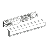
The ABLOY® DB001 and DB002 are electro-hydraulically operated swing door operators. They are designed to open and close doors smoothly, with an AC-motor providing power via a hydraulic unit and an arm system. The closing power is generated by a coil spring, and the movement of the door is controlled by limit switches and valve screws.
Opening: When an opening impulse is received by the control unit, the motor starts and the hydraulic unit rotates the drive shaft and arm system, moving the door towards its open position. Before reaching the fully open position, the speed is reduced to a low speed. The door stops, and the motor rotation ceases when the selected door opening angle is reached. The open position is kept by a hydraulic valve.
Closing: The spring closing starts when the hold open time has run out. Before reaching the fully closed position, the speed is reduced to a low speed, which is kept until the door is completely closed. The door is kept closed by spring power.
Functions of program switch:
- AUTO: The operator opens the door for the duration of the hold open time.
- MAN: Manual use.
- OPEN: The door is held permanently open.
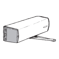
The DB001 is a swing door operator for pushing applications, while the DB002 is for pulling applications. Both models can be configured with standard arms, 50 mm extension pieces, or 20 mm extension pieces, and include a 3-position program switch and a cover.
For double door EMSW applications, the DB020 is a swing door operator for active doors, and the DB022 is for passive doors. These include a full length cover (from hinge line to hinge line) and end plates for the cover. The 3-position program switch is not included in the delivery for these models.
Important Technical Specifications
- Mains power supply: 230 VAC (-10 - +10 %), 50 Hz, fuse 10 A
- Power consumption: max 230 W
- Auxiliary voltage: stabilized 24 VDC, 700 mA
- Motor Fuse: 6,3 AT
- Control unit fuse: 250 mAT
- Class of protection: IP20
- Dimensions: 718 mm x 110 mm x 110 mm (Length, Depth, Height)
- Weight: 15 kg
- Operation: -15...+30°C (in dry premises)
- Automatic swing door operator: Must not be installed in applications where it is subjected to water or snow.
- Recommended door weight/width:
- Standard arm: 250 kg / 1600 mm
- Sliding arm: 100 kg / 1400 mm
- Limit switch (DB102): 1A, 48 VDC, NO
EN1154 Classification:
| Class |
Standard arm Door weight[kg] / width[mm] |
Sliding arm Door weight[kg] / width[mm] |
Closing torque [Nm] (0-4°) |
| 1 |
|
20 / 750 |
9 |
| 2 |
|
40 / 850 |
13 |
| 3 |
60 / 950 |
60 / 950 |
18 |
| 4 |
80 / 1100 |
80 / 1100 |
26 |
| 5 |
100 / 1250 |
|
37 |
| 6 |
120 / 1400 |
|
54 |
Note: The maximum door weight in fire doors, Class 6 door closer will close door 120kg / 1400 mm.
Approvals / Standards:
- Low Voltage directive 73/23/EEC as amended by the directive 93/68/EEC
- EMC directive 89/336/EEC as amended by the directive 92/31/EEC and 93/68/EEC
- The DB swing door operator complies with the door weights/widths stated in the:
- Controlled door closing, EN 1154 size 3-6
- Electrically powered hold-open device for swing doors, EN 1155
- Coordination unit for rebated doors, EN 1158
Usage Features
Installation:
The installation process involves several steps:
- Preparing installation: Checking the proper function of the door (hinges, door clearance) and the lock (lock case, striker plate).
- Installing the mounting plate: The operator is installed on the transom, with the main switch located towards the hinge. The mounting plate DB103 must be level and securely fixed to a flat surface.
- Mounting the operator and the standard arm DB104 to the closing side: This involves attaching the operator with 6 pcs M6x12 screws and adjusting the hold open angle up to 120°.
- Mounting the operator and the sliding arm DB105 to the opening side: Similar to the standard arm, the operator is mounted with 6 pcs M6x12 screws.
- Connecting the operator to mains: Electrical connections must be made by a qualified electrician. A permanent connection is required, equipped with an external switch providing all pole disconnection. Mains must be disconnected during installation.
- Commissioning: Adjustments for opening speed, closing speed, opening angle, closing force, and opening torque are crucial for proper operation.
- Testing: Ensure the door operates as expected after all adjustments.
- Connecting impulse devices: Connect any external impulse devices (e.g., microwave motion sensors, elbow switches, rotary switches) as needed.
Adjustments:
- Opening speed: Adapt the high speed opening HSO to the existing traffic situation. Turning clockwise decreases the speed. The low speed opening LSO is adjusted only if the door is extremely heavy. Turning clockwise decreases the speed.
- Closing speed: The low speed closing LSC is adjusted as the traffic situation allows. Turning clockwise decreases the speed. If a higher closing speed is required, open the high speed closing valve HSC (closed from factory). An additional "lock-kick" can be obtained by adjusting the screw on the hydraulic unit. This screw is normally closed. Adjust by opening the screw 90° and check the function.
- Opening angle: Fine-adjust the opening angle by means of the limit switch. The limit switch is slid into a groove in the hydraulic unit and tightened with a lock screw. By moving the limit switch sideways, the opening angle is changed.
- Closing force: To comply with authority requirements or to overcome over/under pressure, the closing torque can be adjusted. The closing torque (spring force) is adjusted by means of an Allen screw placed at the end of the spring tube. The end plate has to be dismantled.
- Opening torque: If the closing torque (spring force) has been changed, or if the door does not open to its full extent, the opening torque (pump pressure) must be adjusted. The factory set torque for DB104 is 70 Nm and for DB105 is 40 Nm at a door opening angle of 0°. Measure the opening torque by using a spring balance and adjust if necessary. The torque is adjusted by means of an Allen screw placed on the pump. Turning clockwise increases the opening torque/pump pressure. One turn equals a torque change of approx. 30 Nm.
A safe door: The safety of the door operator is controlled by basic adjustments; operator force, speeds, and hold open times. The operator force is an important adjustment. A high value affects the safety feature and also its sensitivity. High speeds increase the energy transferred in the door causing it not to stop correctly. With hold open times, the distance from impulse device to door is preset.
- Adjust low opening and closing speeds.
- Adjust the operator's opening torque and closing force to a low setting.
- Adjust the hold open times.
By following these basic procedures, the operator is safe in operation. High speeds and safety are only possible by fitting of Safety sensors. A safe door environment needs ALWAYS a safety sensor. It is recommended to use safety sensor when possible, not only with high speeds.
Changing the direction of rotation: The direction of rotation can be changed using tool DB110. This involves disassembling and reassembling parts of the drive shaft and bearing sleeves.
Control Unit: The control unit includes a limit switch, magnetic valve, home switch, motor, and capacitor. The limit switch indicates a fully open door and can be adjusted for opening angles up to 120°. The magnetic valve closes and the door is kept open for adjusted hold open time. The home limit switch detects when no home switch is mounted and the limit switch is deactivated in open position, a timer starts and after 6 sec the status will change from closing to closed door.
Potentiometers:
- Hold open time for outer impulse (Outer HOT): Adjustable 0 - 30 seconds.
- Opening delay: Adjustable 0 - 3 seconds. When operator receives opening impulse, lockcase is opened first and door is opened after adjusted delay time.
- Hold open time Key impulse (MVI / Key HOT): Adjustable 0 - 30 seconds.
DIP -switches FS:
- FS1 Kill input: ON means kill input not in use. OFF means when kill is activated, the door will close immediately if not already closed. Hold open and low pass filter timers are reset.
- FS2 and FS3 Operation mode without program switch: Various combinations of ON/OFF for FS2 and FS3 determine the operation mode (e.g., OFF/OFF for TB2:11 and 13 OFF, AUTO; ON/OFF for TB2:11 and 13 AUTO, OFF; OFF/ON for TB2:11 and 13 OFF, OPEN DOOR; ON/ON for TB2:11 and 13 OPEN DOOR, OFF).
- FS4 Lock type: ON for lockcase locked without power. OFF for lockcase locked with power.
- FS5 Activation time for lockcase: ON for lock activation time until door closing. OFF for lock activation time 1,5 s + (opening delay).
- FS6 Slave delay: ON for slave unit opening delay of 0,5 sec. OFF for slave unit standard opening delay of 0,2 sec.
- FS7 Master/Slave: ON for two pieces normal DB operators, Slave operator. OFF for two pieces normal DB operators, Master operator.
- FS8 Push & Go: ON for a push on the door will, from closed position, start an automatic opening cycle if the programme selection is AUTO and remain open during the hold open time "Outer HOT" (0-30 s). A home switch (DB102) on the operator is needed to achieve Push to Go. OFF for Push & Go not in use.
Connection Examples:
- Program selector PS-3A: This connection allows the operator to be in AUTO, OPEN, or MANUAL mode. Outer impulse, opening delay, and key impulse are configurable.
- Kill input: This input can be used to close the door, reset hold open time, and open the lock.
- DA061 and DA062 Microwave motion sensor: Wiring diagrams are provided for connecting these sensors to the control unit.
- DA063 Microwave motion sensor: Wiring diagrams are provided for connecting this sensor.
- DA033 Elbow switch and DA039 and DA049 rotary switch: Wiring diagrams are provided for connecting these switches.
- Extension unit EXB-FI: This unit is mounted on top of the control unit and connects via a flat cable. It provides presence impulse and detection inputs.
- DA001 / DA002 Safety sensor: Wiring diagrams are for connecting these sensors to the EXB-FI unit, with jumper settings for DA001 and DA002.
- Electric locks EL402, EL404, EL502: Wiring diagrams are provided for connecting these electric locks to the control unit and EXB-FI.
- Program switch, motor lock and safety sensor in the opening side of the door: Wiring diagrams are provided for these connections.
- Fire door use: Wiring diagrams are provided for fire door applications, including connections for EL490 and EL590 motor locks.
- Double doors: Wiring diagrams are provided for control units for passive and active doors, including connections for motor control, slave control, and +24 VDC.
Coordinator DB109: This coordinator ensures that rebated doors are closing in the right sequence. Installation instructions include fitting the hook bracket, installing the wire through plastic hoses, mounting the wire wheel, closing the doors, and adjusting the spring tension and closing time.
Push&Go DB116: This unit provides an alternative PC-board fixing and adjustment screw, and includes a Hall switch and magnet.
Maintenance Features
Troubleshooting: The manual includes a comprehensive troubleshooting guide for common faults:
- The door does not open: Possible reasons include program selector set to OFF, motor power missing, main power missing, or impulse device broken. Solutions involve checking settings, cables, fuses, and impulse devices.
- The motor starts: Possible reason is arm system has come loose. Solution is to readjust pre-tension and tighten arm system.
- The door does not open to required angle: Possible reason is limit switch opening has come loose. Solution is to check limit switch.
- The door does not close: Possible reason is constant impulse is created. Solution is to check the impulse device.
- The door does not open fast enough: Possible reason is pump pressure is too low. Solution is to adjust pump pressure.
- The door opens with too much delay: Possible reason is lock-kick valve is opened too much. Solution is to adjust valve screw.
- No smooth braking during operation: Possible reasons include pump pressure too high or low speed distance too short. Solutions involve adjusting pump pressure, increasing opening angle, or increasing pre-tension of arm system.
- High sound level: Possible reason is motor in contact with mounting plate. Solution is to mount two extra screws at the motor side to reduce the mounting plate to the wall.
- The door does not stay open or cannot open: Possible reason is magnetic valve out of operation. Solution involves checking by pressing the pin on top of the magnetic valve. If the door stops, then check the resistance (should be 150 ohm) for the wire between the magnetic valve and the control unit.
Accessories and Spare Parts: A list of accessories and spare parts is provided with their names, codes, and descriptions:
- Tool kit to change rotation direction (DB110)
- Limit switch (DB102) - Safety sensor on the opening side of the door, door closed information
- Mounting plate (DB103)
- Pushing arm (DB104)
- Sliding arm (DB105)
- Extension piece 20mm (DB106)
- Extension piece 50mm (DB107)
- Extension piece 70mm (DB108)
- Arm extension (DB114) - Frame depth < 235 mm
- Arm extension (DB115) - Frame depth > 235 mm
- End plates (DB113) - With DB111, DB112
- Program selector PS-3A (5742075)
- Push&Go (DB116)
- Coordinator (DB109)
- Control unit CSDB + EXB-FI (5742099)
- Control unit for passive door (5742069)
- Hydraulic unit (5742094)
Important Safety Instructions:
- Do not allow children to play with fixed controls.
- Frequently examine the installation for imbalance and signs of wear or damage to cables, springs and mountings. Do not use if repair or adjustment is necessary.
- Disconnect the supply when cleaning or other maintenance is being carried out.
- Before installing the operator, check that the door is in good mechanical condition and it opens and closes properly.
- Ensure that entrapment between door and the surroundings is avoided.
- Ensure that the operator is suited for installation. Check temperature, humidity, door weights, etc. restriction, what is mentioned in this manual or other Abloy® Oy material.
- Instructions, design specifications and illustrations which are contained in this manual are not binding. Rights reserved for changes without previous notice.
- Mount a door stop to the door open position so that wind will not drive the door against the wall, resulting in damage.
- Electrical connections should be made by a qualified electrician.
- The power plug must have an easy access.
- If a permanent connection is made it must be equipped with an external switch providing all pole disconnection.
- Keep the mains disconnected during installation.
- It is important that the high and low voltage cables are well separated and fixed. The high voltage cables must be routed and fixed on one side of the drive unit by using the enclosed cable holders and the low voltage cables must be routed on the opposite side using the same type of cable holders.
- Keep the mains disconnected, while changing dip switch.