R
SETTABLE FUNCTIONS OF EL420 ENGLISH
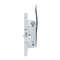
CHANGING THE FOREND Fig. A
1. Set the lock case forend up on the table.
2. Unscrew the fixing screws and remove the forend. Please note that the double action
bolt and its two bushings do not fall off.
3. Set another forend and screw in the screws. Use LOCTITE 243 on each fixing screw.
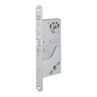
REMOVING THE MANIPULATION PROTECTION COVER Fig. B
CHANGING THE HANDING OF THE TRIGGER BOLT Fig. C (Needed tool: 2.5 mm Allen key)
1. Locate the Allen key between the two springs in the back of the lock case in the Allen
screw-head of the trigger bolt (Fig. C1).
2. Loosen the Allen screw, so that the trigger bolt moves forward and can be turned around
(Fig. C2). Please note not to unscrew the Allen screw.
3. When the handing of the trigger bolt is set, tighten the Allen screw (Fig. C3).
When the handing has been changed, attach the manipulation protection cover.
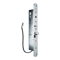
ATTACHING THE CABLE Fig. D
1. Unscrew the fixing screw and remove the cable clamp.
2. Connect the cable into the connector. Fix the cable clamp.
SETTING 8/9 SNAP SPINDLE ADAPTERS Fig. H
8/9 snap spindle adapters are set if the lock case is installed with 8mm spindle. The adapters
must be set on the both sides of the lock case.
There are two flat sides and two sides with a cup in an adapter. The round markings on the
handle follower of a lock case denote the direction, in which the adapter is set. With the mo-
tor locks the direction of the adapter has to be noticed!
SETTABLE FUNCTIONS OF EL520
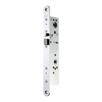
CHANGING THE FOREND Fig. E
1. Unscrew the fixing screws and remove the forend.
2. Set another forend and screw in the fixing screws. Please note that a screw below the
dead bolt is longer than the other screws. Use LOCTITE 243 on each fixing screw.
CHANGING THE HANDING OF THE TRIGGER BOLT Fig. F (Needed tool: 2 mm Allen key)
1. Press the trigger bolt inside the lock case until the Allen screw of the trigger bolt is
shown on the cover side of the lock case.
2. Unscrew the Allen screw.
3. Pull out the trigger bolt and turn it around.
4. Put the trigger bolt back in its place and press it inside the lock case.
5. Screw in the Allen screw.
ATTACHING THE CABLE Fig. G
1. Connect the cable in the connector.
2. Use a cable tie to fix the cable to the lock case. Cut the cable tie short.
SETTING 8/9 SNAP SPINDLE ADAPTERS Fig. H
8
 Loading...