R
WIRING DIAGRAM
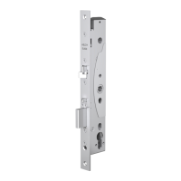
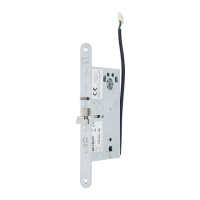
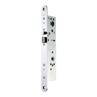
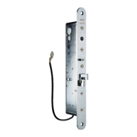
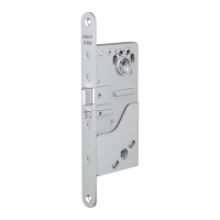
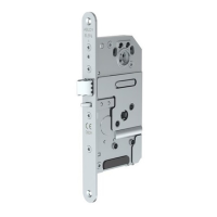
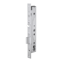
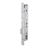
EL420, EL422, EL520, EL522
12 - 24 V DC +/-15%
12 - 18 V AC -10%/+15%, RMS
Red
Black
External connection
for Backup-card
Connection cable ABLOY
EA218 / EA219
Length 6 m/ 10m
18 x 0.14 mm2
Potential free
control
Relays of control unit when:
- Door closed
- Handle not used
- Key cylinder not used
- Bolt not in
- Bolt out
Monitoring cable
sabotage loop *)
*) Potential free loop is closed
when connection cable is con-
nected to lockcase.
Copyright
©
Abloy Oy Joensuu Factory
R
7
Monitoring
Potential free relay contacts
 Loading...