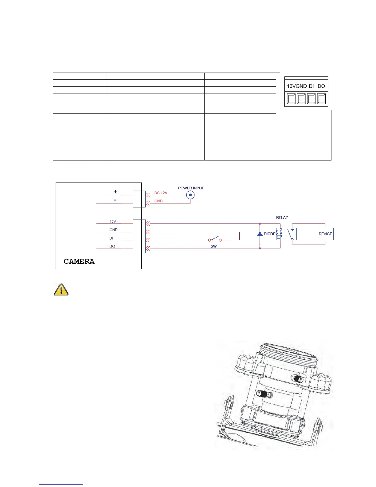
68
4.4 Alarm input and output
Adhere to the following connections and maximum loads for the digital
alarm input and output.
Connection Description Max. load (V/A)
12 VDC Voltage output 12 VDC, max. 100 mA
GND Ground connection -
DI – Alarm input Activation of the digital input
by connecting the DI and
GND connections
-
DO – Alarm
output
Connection of a transistor or relay:
Transistor: NPN with emitter
against ground (GND)
Relay: 12 VDC “and”
connection, plus
DO with diode
(see example below)
24 VDC, 100 mA
Connection example:
Please carefully observe the connection instructions and power specifications!
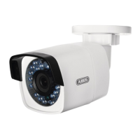
4.5 Setting the zoom and focus
The TVIP71501 and TVIP71551 camera models are
equipped with a variofocal lens. One setting screw for
the zoom and one for the focus are found on the bottom
of the variofocal lens. These screws are also used for
fixing the lens.
Turn the screws carefully anti-clockwise to loosen them.
Make the required settings, then fasten both screws
again.