Do you have a question about the Access IS LSR118 and is the answer not in the manual?
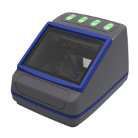
General description of the Access-IS LSR118, its features, and applications in kiosks and gates.
Details physical, environmental, power, and interface specifications of the LSR118 device.
Lists part numbers for LSR118 configurations and associated cables.
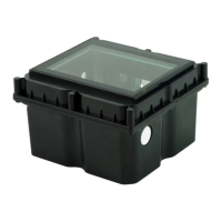
Instructions for unpacking the LSR118 device and verifying included items.
Guides for connecting the LSR118 to a host system via RS232 or USB.
Guidance on mounting the LSR118 device, including dimensions and mounting points.
Details options for connecting the barcode imager interface, including serial and USB.
Describes options for connecting the NFC module, including serial and USB (CCID/HID).
Step-by-step guide for installing the serial barcode module.
Step-by-step guide for installing the USB barcode module with different interface options.
Step-by-step guide for installing the serial NFC module.
Step-by-step guide for installing the USB NFC module.
Instructions for testing the LSR118 device after installation.
Details using configuration software to set up the barcode reader.
Explains communication with the NFC module using Windows Smartcard API.
Provides solutions for common problems encountered with the LSR118 device.
Covers cleaning and storage guidelines for the LSR118 device.
Summarizes the three barcode operating modes: Dumb, Host, and Interactive.
Describes the one-way Dumb mode where the imager sends data to the host automatically.
Explains the two-way Host mode where the host accepts or rejects scanned barcode data.
Details the Interactive mode where the host fully controls the imager and illumination.
Covers commands for setting device interface, connection parameters, and operating mode.
Explains commands for adding prefixes and suffixes to barcode data for custom formatting.
Details commands for controlling the imager's illumination settings and adaptive modes.
Provides commands for managing the 'Good Read' and 'Bad Read' LED behaviors.
Lists commands for firmware, imager levels, and status LEDs for development purposes.
Describes commands to control the triggering and untriggering of the barcode imager.
Explains commands to display and manage 'Good Read' and 'Bad Read' counters.
Outlines the NFC operation process: card detection, ATR retrieval, and communication.
Details serial communication parameters and slot ID mappings for the NFC module.
Explains serial notifications and CCID data exchange formats.
Describes MIFARE card types and identification via ATR bytes.
Covers communication with smartcards via APDU commands using the Windows Smartcard API.
Command to retrieve MIFARE media type and Unique Identifier (UID).
Command to load MIFARE key for sector access and authentication.
Command to authenticate a MIFARE block using Key A or Key B for data access.
Command to authenticate and read data from a specified MIFARE block.
Command to authenticate and write data to a specified MIFARE block.
Command to authenticate and create a value block, initializing it with a 32-bit value.
Command to authenticate and increment the value in a MIFARE value block.
Command to authenticate and decrement the value in a MIFARE value block.
Command for reading blocks from MIFARE Ultralight cards with 4-byte blocks.
Command for writing data to blocks on MIFARE Ultralight cards.
Performs the first part of the MIFARE Ultralight-C authentication process.
Completes the MIFARE Ultralight-C authentication process with the second part.
Allows direct, low-level sending and receiving of raw data to MIFARE media.
Lists and describes status codes indicating failures for MIFARE command operations.
Retrieves the current firmware version of the NFC module.
Retrieves the bootloader version of the NFC module.
Command to switch the NFC module to bootloader mode for firmware updates.
Retrieves the unique serial number of the NFC module.
Configures operating timings for the NFC reader, such as RF reset times.
Retrieves the current operating timings configured for the NFC reader.
Puts the NFC module into sleep mode, switching off the RF field.
Resumes normal operation by exiting sleep mode and turning the RF field back on.
Retrieves the NFC kernel version of the NFC module.
Retrieves the serial number or unique identifier of the detected NFC media.
Disables notifications for media arrival/removal events from the NFC module.
Changes the baud rate for the serial interface communication.
Explains matching NFC module serial numbers for physically present readers in multi-module systems.
Details the structure of HID input reports for data received from the LSR118 barcode imager.
Describes HID output report structure for sending commands to the LSR118.
Explains using HID output reports to control device status and activate read lights.
Provides code snippet for establishing the smartcard sub-system context.
Shows code for polling the smartcard reader to detect card presence or removal.
Example code for connecting to a detected smartcard.
Provides code to retrieve the Answer to Reset (ATR) from a smartcard.
Example code demonstrating communication with a connected smartcard.
References section on identifying MIFARE card types based on ATR.
Code snippet for safely disconnecting from a smartcard.
Provides a reference table of ASCII characters, their decimal, hexadecimal, and symbolic representations.
Lists revisions, dates, and descriptions of changes made to the product manual.
| Connectivity | Wired |
|---|---|
| Power Supply | 5 VDC |
| Operating Temperature | 0°C to 50°C |
| Scanning Speed | Up to 60 fps |
| Interface | USB, RS232 |
| Storage Temperature | -20°C to 70°C |
| Humidity | 5% to 95% (non-condensing) |