Installation & Operation Manual - Model AVC5000
Contents of this Manual are Subject to Change Without Notification Page 23
6.6.4 Operating Modes
The AVC5000 has two different Modes of Operation; Setpoint Mode and Fume Hood Mode. The
Mode of Operation is factory-configured, therefore it’s unlikely that it will need to be changed
in the field; however it can be changed if required. A description of each Operating Mode and
their associated parameters are provided below.
6.6.4.1 Setpoint Mode
Setpoint Mode is used for all applications with the exception of fume hood applications which
use the AFC5000 Fume Hood Display Module. Within Setpoint Mode, there are three different
options for how the airflow setpoint can be provided to the controller; Analog Input (AI-1), Dry
Contact Inputs (DI-1, DI-2) or BACnet MS/TP Communications. The factory default values for
Setpoint Mode are provided in Appendix C. The following examples show how to configure
each setpoint source and their associated parameters.
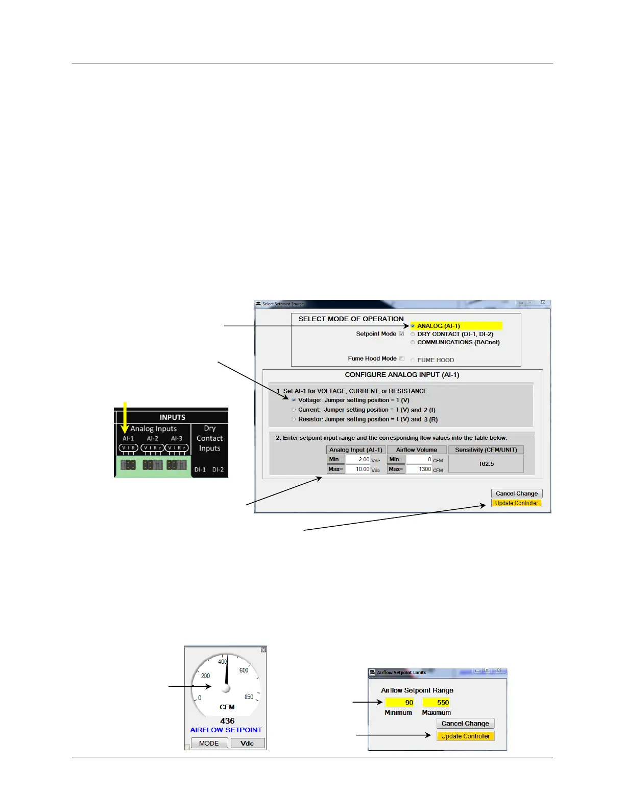
6.6.4.1.2 Setpoint Source = Analog Input (AI-1)
Selecting Analog Input AI-1 will configure the controller to receive the airflow setpoint from
Analog Input AI-1.
6.6.4.1.2.1 Setting Min and Max Volume Limits on the Setpoint
When the setpoint source is configured for “Analog”, setpoint limits can be applied without
changing the analog input scaling. To set min/max setpoint limits, double-click the Airflow
Setpoint Gauge Face, which will open the dialog box shown below on the right. Enter the
desired minimum and maximum limits and select Update Controller to save the changes.
These values will also appear on the PID graphic as a Tool Tip for the displayed SETPOINT value.