System Board 1-11
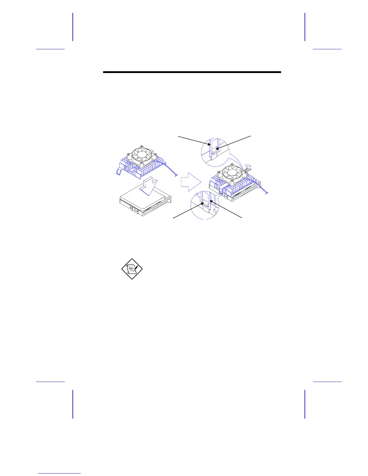
4. Place the CPU heat sink and fan over the CPU.
5. Link the front heat sink hook to the holding tab on the front edge
of the CPU socket, then the rear hook to the rear holding tab.
This locks the heat sink and fan to the CPU socket.
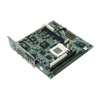
Figure 1-6 Installing the CPU Heat Sink and Fan
To remove the heat sink and fan, simply
press the upper part of the rear hook inward.
6. Attach the CPU fan cables to the connectors on the board.
7. Change the settings of jumper JP1 for the correct CPU voltage
and jumpers JP4, JP5, and JP7 for the CPU frequency. Refer to
Table 1-1 for the jumper settings.
Holding Tab (rear)Heat Sink Hook (rear)
Heat Sink Hook (front)
Holding Tab (front)