1-4 User’s Guide
1.3 Jumpers and Connectors
1.3.1 Jumper and Connector Locations
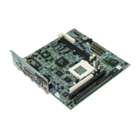
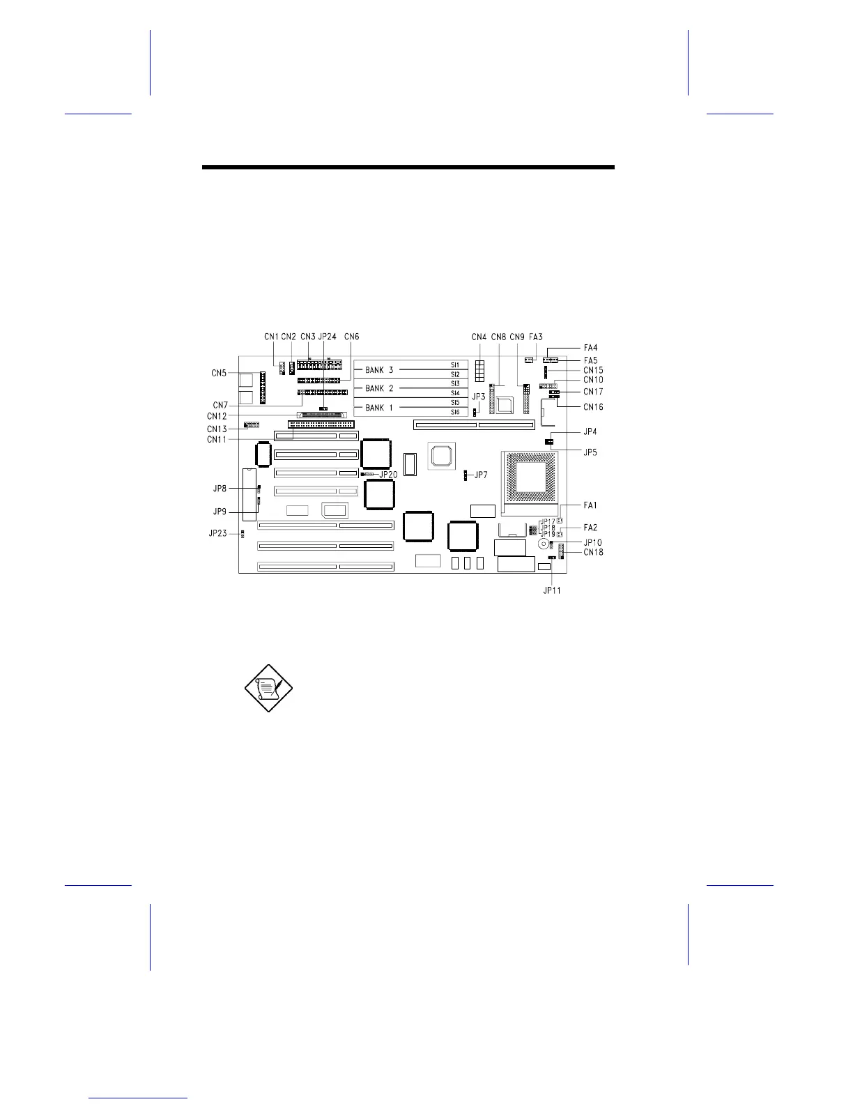
Figure 1-2 shows the jumper locations on the system board. The
blackened pin on a jumper represents pin 1.
Figure 1-2 Jumper Locations
Jumpers are prefixed “JP”. Connectors are
prefixed “CN”. FA1 to FA5 are fan
connectors.
The blackened pin of a jumper represents
pin 1.