Do you have a question about the Acer 486 and is the answer not in the manual?
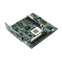
Details the major components of the system board.
Essential safety guidelines to prevent damage from electrostatic discharge.
Steps to follow before installing system components, including safety.
Explains jumper locations and functions for system configuration.
Guide to installing and configuring memory modules (SIMMs) on the system board.
Step-by-step instructions for correctly inserting a SIMM module into its socket.
Procedure for safely removing SIMM memory modules from the system board sockets.
How the system detects installed memory and how to verify it.
Instructions for upgrading the Central Processing Unit (CPU) on the system board.
Guidance on unpacking and inspecting the new CPU and its accompanying components.
Detailed steps for safely installing a new CPU into the system board socket.
Explains the purpose and installation of the power daughter board for 3.3V microprocessors.
Instructions on how to increase the Video Graphics Array (VGA) memory capacity.
Guide on how to install additional cache memory chips to improve system performance.
Final checks and steps to ensure system stability after component installation.
Overview of the system's power-saving features and supported modes.
Details on using the Advanced Power Management (APM) standard for power reduction.
Information about Intel SL-Enhanced CPUs and their support for System Management Mode.
Explanation of the VESA Display Power-Management Signaling (DPMS) standard for monitors.
Information on identifying and understanding various software and system error messages.
Describes software error messages and how to resolve them using application manuals.
Lists system error messages during power-on self-test and their corrective actions.
Provides corrective measures for common system errors and configuration issues.
This document describes a system board, focusing on its features, installation procedures for various components, and troubleshooting.
The system board is a high-performance, 32-bit personal computer system based on the 486 series microprocessor. It incorporates single-chip upgrade technology for easy and flexible system upgrades. It is fully compatible with the IBM PC/AT and is suitable for use as a Windows workstation, CAD/CAE/CAM workstation, UNIX personal workstation, or desktop PC.
The system board supports a LAN environment with 16-bit Arcnet, Ethernet, and Token Ring cards. It is fully compatible with Novell NetWare, Microsoft LAN Manager, SCO UNIX, XENIX, and OS/2 operating systems.
It includes several software-controlled security features such as power-on password, disk drive read/write control, diskette boot control, serial- and parallel-port control, and a system setup control.
The mainboard also integrates power-conservation technology, requiring an Intel SL-Enhanced or power-saving CPU to utilize its energy-saving capabilities. The Power-Management feature monitors system activity (keyboard, mouse, diskette drives, fixed disk drives, connected peripherals, or video memory) and switches to power-saving modes after a specified inactivity time-out.
CPU:
Memory:
Cache Memory:
VGA:
Ports and Interfaces:
Chips:
Power Management Modes:
Advanced Power Management (APM):
VESA DPMS Modes:
System Upgrade Flexibility:
Jumper Settings:
Power Management:
Error Messages:
Installation Procedures:
Troubleshooting:
Post-installation Instructions:
| Brand | Acer |
|---|---|
| Model | 486 |
| Category | Motherboard |
| Language | English |