1-2 User’s Guide
1.1 System Board Layout
The system board has the following major components:
•
486SX, SX2, DX2, or DX4 series CPU
•
4-MB onboard RAM expandable to 36 MB
•
Two 72-pin SIMM sockets for memory upgrade
•
128-KB ROM for system BIOS and VGA BIOS
•
120-pin connector for ISA riser card
•
System clock/calendar
•
Two 9-pin serial ports
•
One 25-pin Centronics parallel port
•
PS/2-compatible keyboard and mouse interface
•
512-KB or 1-MB DRAM for onboard local bus VGA interface;
expandable to 1 MB (for GD-5424) or 2 MB (for GD5429)
•
Embedded fixed disk interface
•
Upgradable cache memory (128-KB or 256-KB)
•
Optional enhanced IDE interface
•
Optional power daughter board that enables the system to
support the 3.3V microprocessors
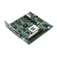
Figure 1-1 shows the board layout and the locations of the important
components.