Service and Maintenance 5-30
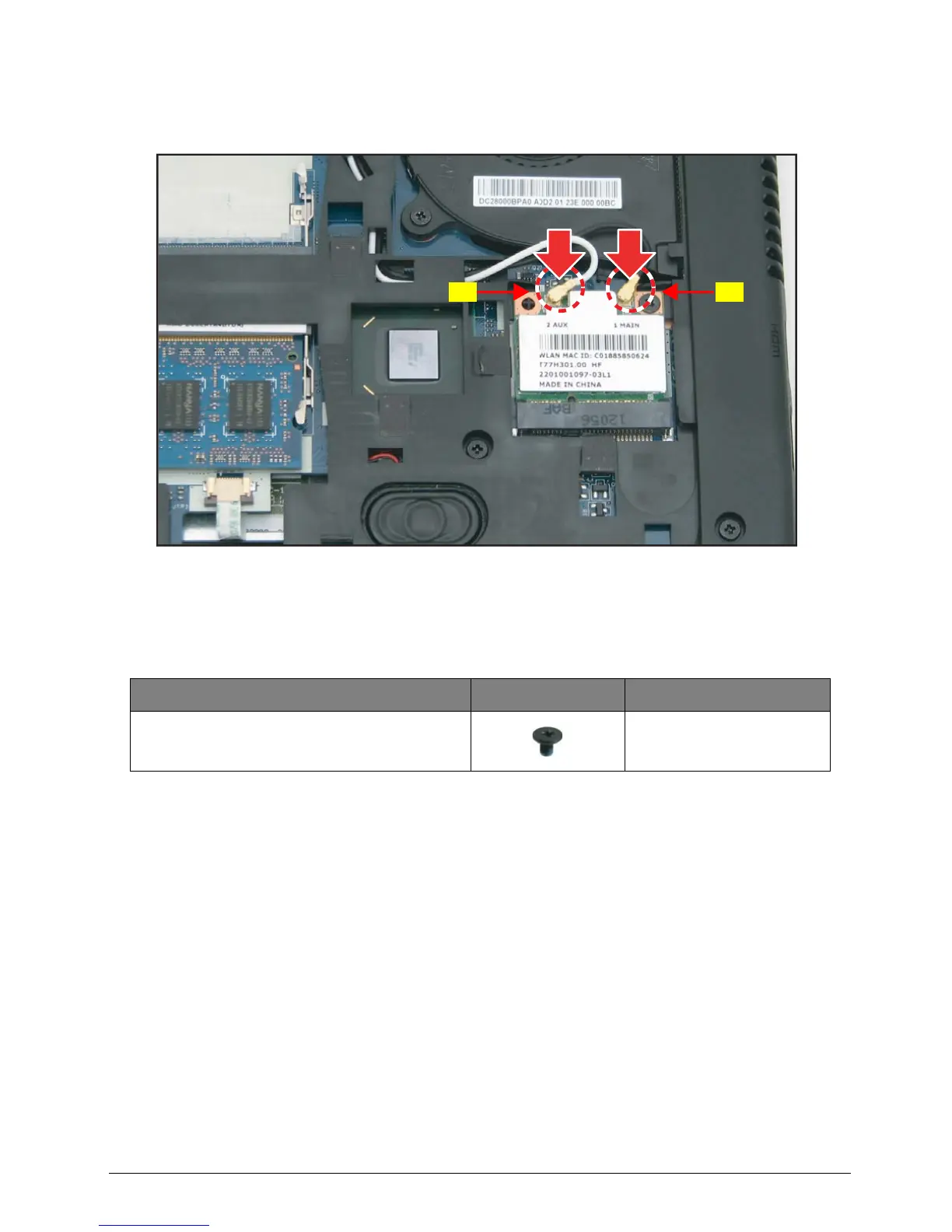
3. Connect the antenna cables to the WLAN module connectors:
• Auxiliary (A - white) antenna cable to the left connector.
• Main (B - black) antenna cable to the right connector.
Figure 5:38. Securing the WLAN Module Screw
4. Install the base door (see Base Door Installation on page 5-13).
Table 5:11. WLAN Module Screw
Screw Name Screw Type Quantity
M 2.0 x 3.0 1

 Loading...