Do you have a question about the Acer KA270H and is the answer not in the manual?
Detailed visual representation of product components for identification and assembly.
Step-by-step instructions for taking the product apart.
Step-by-step instructions for putting the product back together.
This document serves as a Lifecycle Extension Guide for the Acer Monitor KA270H, providing comprehensive instructions for its disassembly, assembly, troubleshooting, and identification of Field Replaceable Units (FRUs). The guide is designed to assist service providers in performing proper and safe maintenance and repair procedures, ensuring the continued reliable operation of the product.
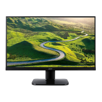
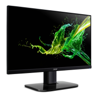
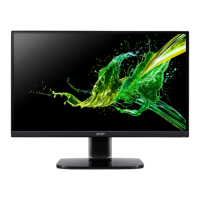
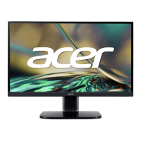
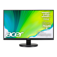
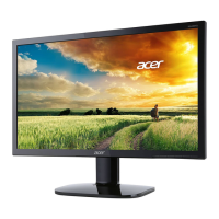
The Acer Monitor KA270H is a display device designed for various computing needs. Its primary function is to provide visual output from a computer or other video sources. The monitor is constructed with several key components, including a mid-frame, control board (PCBA CTRL BD), LCD module (LCDM 27W AUO M270HVN02.3Q0 Z), power supply board (PCBA SPS BD), interface board (PCBA IF BD), and various wiring and shielding components. The monitor is designed to be serviceable, allowing for the replacement of defective parts to extend its operational lifespan.
The monitor offers standard display functionalities, with connectivity options that may include USB, depending on the specific SKU. The internal wiring diagrams illustrate how different components, such as the interface board, power board, control board, and USB board (if present), are interconnected. The guide details two main SKU configurations: one with USB connectivity and one without, indicating variations in internal wiring. Users can adjust display settings through an On-Screen Display (OSD) menu, which allows for modifications to brightness, contrast, resolution, clock, clock-phase, H-position, and V-position. This flexibility helps in optimizing the visual output for different content and user preferences. The monitor also includes audio capabilities in some models, allowing for sound output when connected to a host PC.
The Lifecycle Extension Guide emphasizes safe and proper maintenance practices. It begins with an "Important Safety Notice" that highlights the product's compliance with RoHS Directive and Lead-Free production definitions, recommending the use of approved critical components for replacement. Service providers are advised to familiarize themselves with the chassis and necessary safety precautions, especially when dealing with high voltage components. The guide stresses the importance of using original manufacturer's specified parts to ensure continued reliability.
The manual provides a detailed, step-by-step Standard Operating Procedure (SOP) for both disassembly and assembly. Before any procedure, a clean working environment is required, and the service provider must prepare specific tools, including Philips-head and Hex-head screwdrivers, a knife, gloves, cleaning cloth, and ESD protection. A critical safety warning is issued regarding the power board, which can retain energy even after being unplugged.
A comprehensive troubleshooting section is provided for both VGA and HDMI/DP modes. It lists common problems, their current status (e.g., LED ON, LED OFF, LED displays amber color, Unstable Picture, Display missing/shifted/sized incorrectly, No sound/low sound), and corresponding remedies.
The guide includes a "Field Replaceable Unit (FRU) List" for the Acer KA220H (note: the document title refers to KA270H, but the FRU list mentions KA220H, which might be a typo or indicate shared components). This list provides categories (LCD, BOARD), Acer descriptions, general descriptions, and part numbers for ordering replacement parts. Service providers are cautioned to check the most up-to-date information on regional web or channel resources, as part numbers may change. Local FRU lists from regional offices should be used for ordering. Instructions for proper disposal or return of defective parts according to local government ordinances or regional office rules are also included.
Overall, this guide is an essential resource for extending the life and maintaining the performance of the Acer Monitor KA270H through detailed repair and maintenance procedures.
| 3D | No |
|---|---|
| Panel type | VA |
| Pixel pitch | 0.311 x 0.311 mm |
| Screen shape | Flat |
| Pixel density | 82 ppi |
| Display surface | Matt |
| Display diagonal | 27 \ |
| Display technology | LED |
| Native aspect ratio | 16:9 |
| Maximum refresh rate | 60 Hz |
| Contrast ratio (dynamic) | 100000000:1 |
| Contrast ratio (typical) | 3000:1 |
| Display number of colors | 16.78 million colors |
| Display brightness (typical) | 300 cd/m² |
| Supported graphics resolutions | 1920 x 1080 (HD 1080) |
| On/off switch | Yes |
| Product color | Black |
| Market positioning | - |
| Tilt angle range | -5 - 35 ° |
| Panel mounting interface | 100 x 100 mm |
| Energy efficiency scale | A to G |
| Power consumption (off) | 0.24 W |
| Power consumption (standby) | - W |
| Power consumption (typical) | 32 W |
| Harmonized System (HS) code | 85285210 |
| Depth (without stand) | 192 mm |
|---|---|
| Width (without stand) | 567 mm |
| Height (without stand) | 435 mm |
| Weight (without stand) | 3740 g |