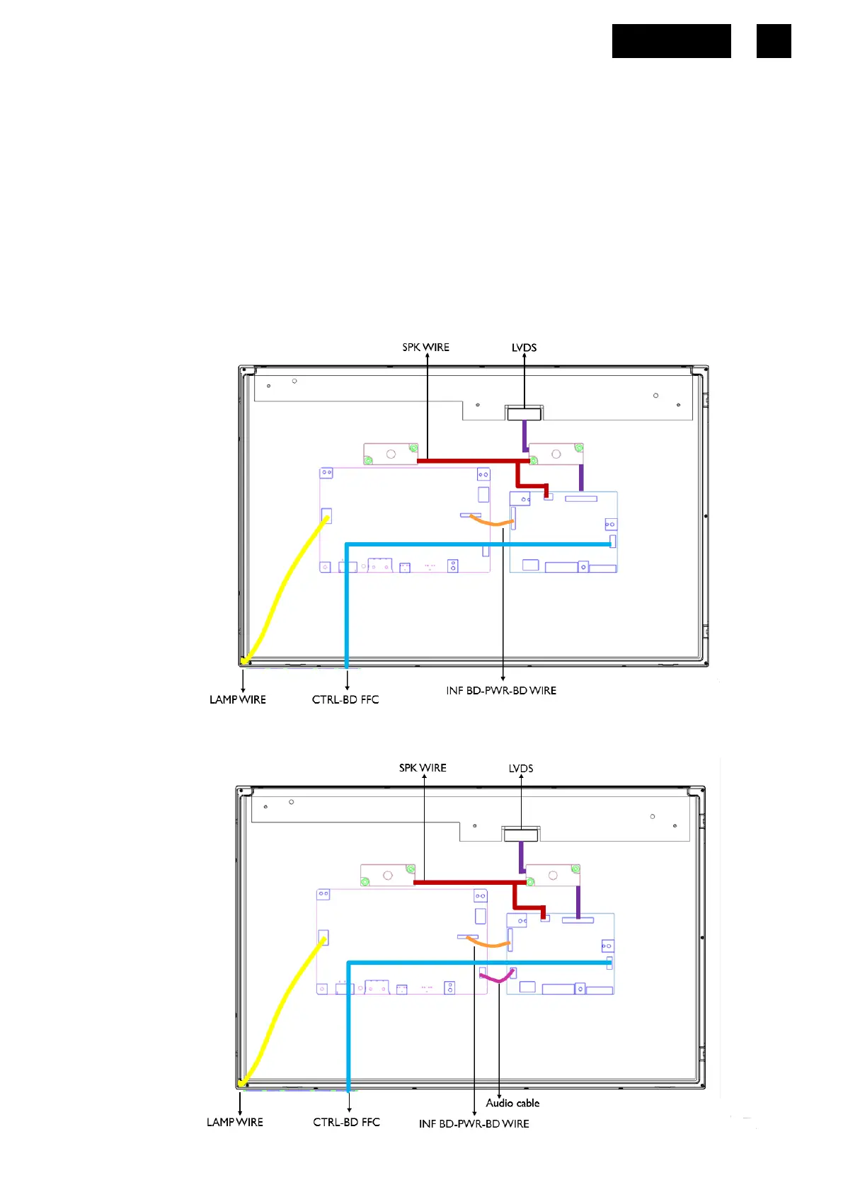
2. Wiring connectivity diagram
There are four types of wiring diagrams for model V176L. The wiring connectivity position will be
different according to the ACTUAL PCBA connector position. Please base on different SKU refer to
below diagram.
NOTE: INF BD= Interface Board, PWR BD=Power Board, CTRL BD= Control Board
1. SKU without USB, without HDMI/DP
2. SKU without USB, with HDMI/DP
 Loading...