DSIM-CC & DSIM-CF
Setup Guide Rev E
LED Fault Conditions Blinking Patterns
24 volt input into DSIM module is out of the
operational range of 21.5 to 26.5 VDC. If this
occurs, check for correct AC voltage input to the
amplifier and for correct output DC voltage of
internal power supply to the RF module
Steady Repeating Orange Blinks
Temperature in DSIM module is too high / low
(above 221ºF/105ºC or below -40ºF/-40ºC)
Quick Blue / Orange Blinks
Pilot Lost; DSIM automatically switches to
Thermal (TGC) mode until Pilot channel is
restored
Note: The DSIM LED blinks after the pilot channel count will be orange during programming
and blue when in operation.
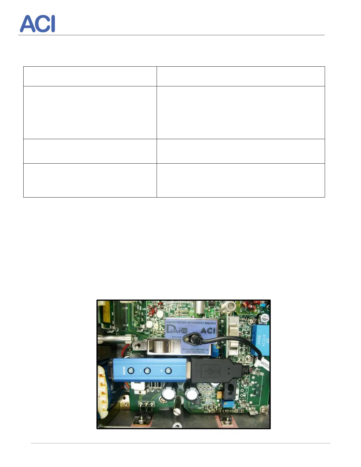
7. DSIM Interface Cable Assembly
To make the connection from the DSIM controller to the DSIM AGC module use cable
assembly P/N 240330-01 as shown below. Plug in Controler cable, then plug the controller
into the cable. Same for removal. Remove the controller from the cable then remove the
cable from the DSIM. Note: The RF module is shown with faceplate cover removed for
clarity.