12 13
CAUTION
At elevated VSWR levels, high voltages and high currents are distributed along the
coaxial cable to the antenna, risking internal arcing and heat generation, and likely
damage to the cable and any antenna switches that may be used. It is recommended
that VSWR levels of more than 3:1 not be permitted with coaxial cable above
14 MHz.
It is advisable to adjust amplifier tuning when antennas have been changed, snow has fallen, new objects
are in the near field of the antenna, etc. Such changes may affect antenna impedance.
NOTE
If you use more than one antenna on a band, the proper antenna must be selected
prior to performing the tuning procedure outlined below.
CAUTION
To avoid damage not covered under warranty, do not switch the BAND switch knob
while transmitting. As discussed above, hot switching will damage the amplifier’s
band switch!
CAUTION
Also, never apply drive longer than one minute continuously without pausing for at
least one minute to allow the tube to cool.
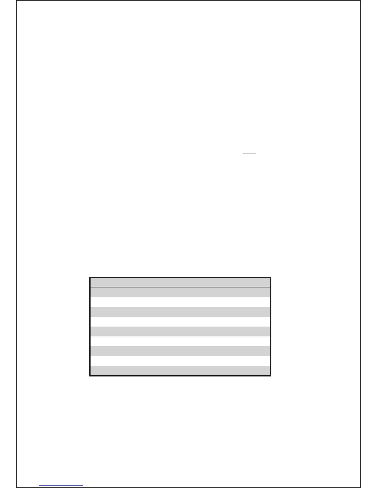
It is recommended that for initial tuning a frequency in the middle of the band be used. First, with no
transceiver power applied, select the band. Then use Table 4-1 to achieve an approximate preset for
both TUNE and LOAD capacitor knob settings:
Band MHz LOAD Knob Dial TUNE Knob Dial
1.800 - 2.000 47 - 71 54 - 32
3.500 - 4.000 34 - 56 51 - 33
7.000 - 7.300 32 - 39 36 - 30
10.100 - 10.150 62 - 63 50 - 48
14.000 - 14.350 37 - 41 38 - 31
18.068 - 18.168 41 - 43 50 - 48
21.000 - 21.450 59 - 62 16 - 10
24.890 - 24.990 50 - 52 49 - 46
28.000 - 29.700 63 - 69 23 - 10
Table 4-1. Approximate tuning preset
b) Tuning Procedure.
(1) Once the antenna and band have been selected (and the TUNE and LOAD adjustments have
been initially set as indicated in Table 4-1), apply between 10 and 20 W of continuous (key down CW)
signal.
(2) Look at the upper LED bar-graph (FORWARD POWER) and adjust the TUNE (right hand) capacitor
for maximum indication.