12 13
(3) Watch the TRI indicator above the LOAD (left hand) capacitor and turn the LOAD capacitor in the
indicated direction to center the green LED indicator light.
(4) Increase the drive power to get the desired nominal output; then repeat steps (2) and (3), always
peaking output with the TUNE adjustment.
NOTE
No light on the TRI indicator means that the tuning is too far off. To correct this,
turn the LOAD and TUNE knobs around the table-suggested positions until the TRI
indicator illuminates.
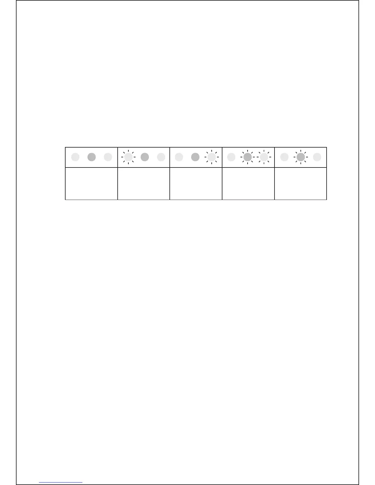
no light:
use TUNE knob
for max. Power
to get any marker
tuning is far left:
turn LOAD knob
to the right to get
the inside markers
tuning is far right:
turn LOAD knob
to the left to get
inside markers
marker inside:
turn LOAD knob
slightly left
to center it
LOAD is tuned:
turn TUNE knob
to peak Forward
Power
Fig. 4-1. Using TRI tuning aid
The TRI indicator will not illuminate until at least 20 W of forward power (output) is achieved. In the event
successful matching cannot be accomplished, check the BAND switch position and antenna selection.
Then check the antenna VSWR at the same drive frequency.
d) Tuning hint. A benefit of TRI is that the knob positions are virtually independent. The plate-load
resistance decreases to the right and increases to the left of the TRI center. A centered tuning indication
corresponds to the proper LOAD capacitor tuning, which presents an optimum load resistance to the
tube.
If the LOAD knob is turned to the left with a centered TRI, there will be more gain, but less linearity.
When available drive power is insufficient or when less output but better efficiency are needed, e.g.,
for RTTY and SSTV, this may be desirable. Tuning to the right of the center would lead to the opposite
result, i.e., less gain and more power attainable. Of course, this requires more drive power, more plate
current, and more plate heat, which shortens tube’s-expected life. Off -center tuning may also be used to
compensate for line (mains) voltage variations in order to maintain tube efficiency. In that case, tune to
the left when line (mains) voltage is high, or tune to the right if it is low. However, where there is more
than a 10% difference from the nominal line (mains) voltage, the voltage selector inside the amplifier
should be changed. See Section 2-2 (Line Voltage Selection).
4-6 The Auto-Protection System
When any abnormal amplifier condition is detected by the auto-protection microprocessor, the risk will
be evaluated automatically and either of two levels of protection will be applied:
a) The first degree of protection consists of an illuminated LED warning. These include the yellow
LED warnings discussed earlier, i.e., “G1” (grid 1), “G2,” (grid 2), and “IP” (plate). Operation may be
continued but the amplifier is likely to proceed to the second degree of protection, the trip.
b) The second degree of protection is a trip to the standby mode. The red “F” (fault) LED illuminates
and the amplifier automatically goes to the standby mode for several seconds. Also, the green OPER
LED goes off. The amplifier will indicate the reason for the protection trip: