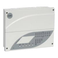
The CB200 Conventional Control Panel is a fire alarm control panel designed for conventional fire detection systems. It is available in 1, 2, 4, and 8 zone configurations, offering flexibility for various installation sizes and requirements. The panel is housed in a polycarbonate cabinet with a satin textured light grey (RAL7035) finish, providing a durable and aesthetically pleasing enclosure. Eleven top-entry grommets are provided on a removable gland plate for cable management.
Physical Dimensions (for the standard cabinet):
- Back box height (a): 235mm
- Back box width (b): 287mm
- Back box depth (c): 66mm
- Front cover height (d): 245mm
- Front cover width (e): 313mm
- Bezel overhang - top/bottom (f): 5mm
- Bezel overhang - left/right (g): 13mm
- Protection plugs: 11
Technical Specifications (vary by zone configuration):
CB200 1-2 Zone Control Panel:
- Maximum field equipment load: 800mA
- Auxiliary 24VDC output: 250mA
- Mains failed current consumption: 35mA
- Integral charger output: 500mA
- Common fire output: Volt-free contacts - 1A, 30V DC max.
- Common fault output: Volt-free contacts - 1A, 30V DC max.
- Alarm circuit output: 2 at 250mA each
- Battery size: 2 x 12V 2.1AH sealed lead acid
- Weight (excluding batteries): 2.3kg
CB200 4 Zone Control Panel:
- Maximum field equipment load: 800mA
- Auxiliary 24VDC output: 250mA
- Mains failed current consumption: 40mA
- Integral charger output: 500mA
- Common fire relay: Volt-free contacts - 1A, 30V DC max.
- Common fault output: Volt-free contacts - 1A, 30V DC max.
- Alarm circuit output: 4 at 500mA each
- Battery size: 2 x 12V 2.1AH sealed lead acid
- Weight (excluding batteries): 2.3kg
CB200 8 Zone Control Panel:
- Maximum field equipment load: 800mA
- Auxiliary 24VDC output: 250mA
- Mains failed current consumption: 40mA
- Integral charger output: 500mA
- Common fire relay: Volt-free contacts - 1A, 30V DC max.
- Common fault output: Volt-free contacts - 1A, 30V DC max.
- Alarm circuit output: 4 at 500mA each
- Battery size: 2 x 12V 2.1AH sealed lead acid
- Weight (excluding batteries): 2.4kg
CB200 8 Zone Repeater Panel with Power Supply:
- Mains failed current consumption: 40mA @24VDC
- Integral battery charger output: 500mA @27.5VDC
- Auxiliary 24VDC output: 250mA
- Battery size: 2 x 12V 2.1AH sealed lead acid
- Weight (excluding batteries): 2.4kg
CB200 8 Zone Repeater Panel Powered from Panel:
- Current consumption: 40mA @24VDC
- Weight: 1.4kg
Usage Features:
The CB200 panel features a comprehensive set of user controls and indications, particularly for the 8-zone model. A slide-in card allows for text-based zone identification.
Indications:
- Zone Fire LEDs: Flash when a zone is triggered into fire, illuminate steady after the "Silence Alarms" button is pressed.
- Zone Fault LEDs: Flash with any zone fault or device removal, illuminate steady when a zone is isolated.
- Alarm Proc Fault LED: Flashes when an alarm circuit is in fault.
- Earth Fault LED: Flashes when an earth fault occurs (4-8 zone only).
- Repeater Fault LED: Flashes when a repeater fault occurs (4-8 zone only).
- One Man Test LED: Flashes when engineer's one-man test is active (4-8 zone only).
- Processor Fault LED: Flashes when a processor fault occurs.
- Supply Healthy LED: Illuminates when both mains and battery supplies are healthy.
- Battery Fault LED: Flashes when a battery supply fault occurs.
- Controls Active LED: Illuminates when controls are active.
User Controls:
- Silence Alarms/Buzzer: Press to silence alarm circuits or the fault buzzer.
- Reset System: Resets the system after alarms have been silenced. Also functions as test LEDs at other times.
- Evacuate: Operates alarm circuits (but not auxiliary fire output). Press to operate, press again to stop.
- Isolate Zone: Allows for the isolation of individual zones.
- Access Control: Press "5" to access user control facility, then press "1-4" to enable controls. Repeat to disable.
Engineer Facilities:
- Mechanical Assembly: The panel's internal layout includes PCB terminals, LED indications, a display cover, user controls, battery leads (red/black), battery space, mains terminals, and a transformer. Fixing screws, a semi-flush keyhole bezel, and a removable gland plate with protection plugs are also part of the assembly.
- Buzzer Enable Link: A link on the top right corner of the Control Board allows for disabling/enabling the buzzer, useful during commissioning. This link is not monitored, so its removal will not generate faults.
- Engineer's Controls (1-2 Zone Panels):
- Processor Reset: Press to reset if the "Processor Fault" LED illuminates.
- One-man Test: If pressed for more than 5 seconds, the panel enters One-man Test mode.
- Zone 1 Non-latch: Setting the zone 1 non-latch DIL switch to ON enables a non-latching fire indication mode for zone 1. In this mode, a fire condition on zone 1 will trigger an indication and alarms, but the auxiliary fire relay contacts will not operate. If the fire condition clears, the indication and alarms for zone 1 will clear, provided no other zones are in fire. If other zones are in fire, the panel remains in fire condition until manually reset.
- Class Change Input: A non-fault monitored, normally open input. A short circuit across these terminals activates alarm circuits and the internal buzzer. This input is non-latching.
- Engineer's Controls (4-8 Zone Panels): Accessible via the Engineer's Access Code, these functions include One-man Test, Earth Fault enable/disable, and Clear Processor Fault indication. The processor will automatically restart unless there's a hardware fault.
CB200 Repeater Panel:
A repeater panel is available for 4 and 8 zone CB200 panels, connecting via RS485 serial communications over a screened twisted pair cable. Up to 3 repeaters can be connected, offering remote indication and control:
- Indication of zonal fire, zonal fault, and zonal isolate conditions.
- Operation of Buzzer Silence, Manual Evacuate, Alarms Silence, and System Reset functions.
- Indication of control panel status.
- Indication of communication fault with the control panel.
- Indication of local power supply fault (if fitted).
- Indication of power supply fault on another repeater (steady Batt. Fault LED).
- Indication of a communication fault on another repeater (steady Comms. Fault LED).
- Note: Only one repeater can be powered from the 24VDC supply output on the control panel.
Repeater Configuration:
- Number of repeaters connected to the panel (set on the panel).
- Repeater address (set on each repeater).
RS485 Cable Specification:
- Generic Type: RS422/RS485 data cable.
- Conductors: Single pair plus screen.
- Alpha cable: 3492C, 6222C, 6412 or equivalent.
- Belden cable: 8102, 8132, 9841 or equivalent.
Important Note on Current for 4 and 8 Zone Panels:
The total available current for field devices is 800mA at 28VDC. This current must be shared between the auxiliary 24VDC supply and the four alarm circuits, ensuring the total current drain across these five circuits does not exceed 800mA.
Panel Enhancements:
The CB200 panel can be enhanced with various compatible products, including:
- C1437 4-way alarm extender board (requires separate PSU).
- A1466 1 x double pole relay board (1A contacts).
- Heavy duty relay boxed (suppressed) (requires additional power supply).
- Enclosures with PSUs and space for expansion boards and batteries (e.g., 1A, 3A, 5A, 10A PSUs with space for C1437, A1466, C1324 boards, and various battery sizes).
Battery Sizes (YUASA):
The CB200 panel is designed to house a 2.1AH battery set. Other suitable batteries for expansion items and auxiliary power supplies include:
- 3.2AH battery 12V: 134 length x 67 wide x 64 high
- 6.2AH battery 12V: 151 length x 65 wide x 97.5 high
- 12AH battery 12V: 151 length x 98 wide x 97.5 high
- 15AH battery 12V: 181 length x 98 wide x 167 high
Compatible Zone Devices:
The CB200 panel is compatible with a wide range of conventional fire detection devices from manufacturers like Apollo, Hochiki, Honeywell, Nittan, System Sensor, Ziton, and KAC. The maximum quantity of devices per zone is typically 32 for detectors and unlimited for manual call points.
Notes on Device Compatibility:
- When using Hochiki smoke detectors (SIHE and SLKE), a 3K9 0.25 watt resistor must be fitted across terminals L1 and S4.
- When using Nittan detectors with RB3R bases, a 220 ohm resistor must be fitted across L and S1.
- All manual call points must have a resistor in the range of 470 Ohm to 680 Ohm fitted to them.
Other Compatible Zone Devices:
- Break glass unit without back box c/w 680 ohm resistor (2501/012)
- Break glass unit with back box c/w 680 ohm resistor (2501/013)
- Remote square indicator (2500/226)
- Remote round indicator (2500/227)
- Spare glasses for break glass units (pack of 5) (2501/014)
General Accessories:
- 2.1AH S.L.A. battery set (2 x 12V) (2501/032)
- 150mm bell (24 volts DC) (2501/040)
- Roshni Electronic Sounder (24 volts DC) (2501/044)
- Xenon flashing beacon (24 volts DC - 2 watts) (2501/043)
- Door retainer (24 volts DC) - auxiliary power supply required (2501/033)
- Door retainer (230 volts AC) (2501/034)
- Door retainer floor bracket (2501/035)
- Various power supply units in enclosures with space for batteries (e.g., 1A, 3A, 5A, 10A PSUs).
Maintenance Features:
The panel includes a "Buzzer Enable Link" for commissioning, allowing the buzzer to be temporarily disabled. The "Processor Reset" function helps in clearing processor faults. The "One-man Test" mode simplifies testing procedures for engineers.
Additional Documentation:
Further information is available through Sales Literature, Installation & Commissioning Manual, User Instructions, Wiring Recommendations, and an After-Sales Technical Support Booklet.