Written by: R Patel Checked by: AJC
Document No.: CBAPP Rev.: 7 Page 4 of 11 Date: 06/06/2003
2.2 Engineer Facilities
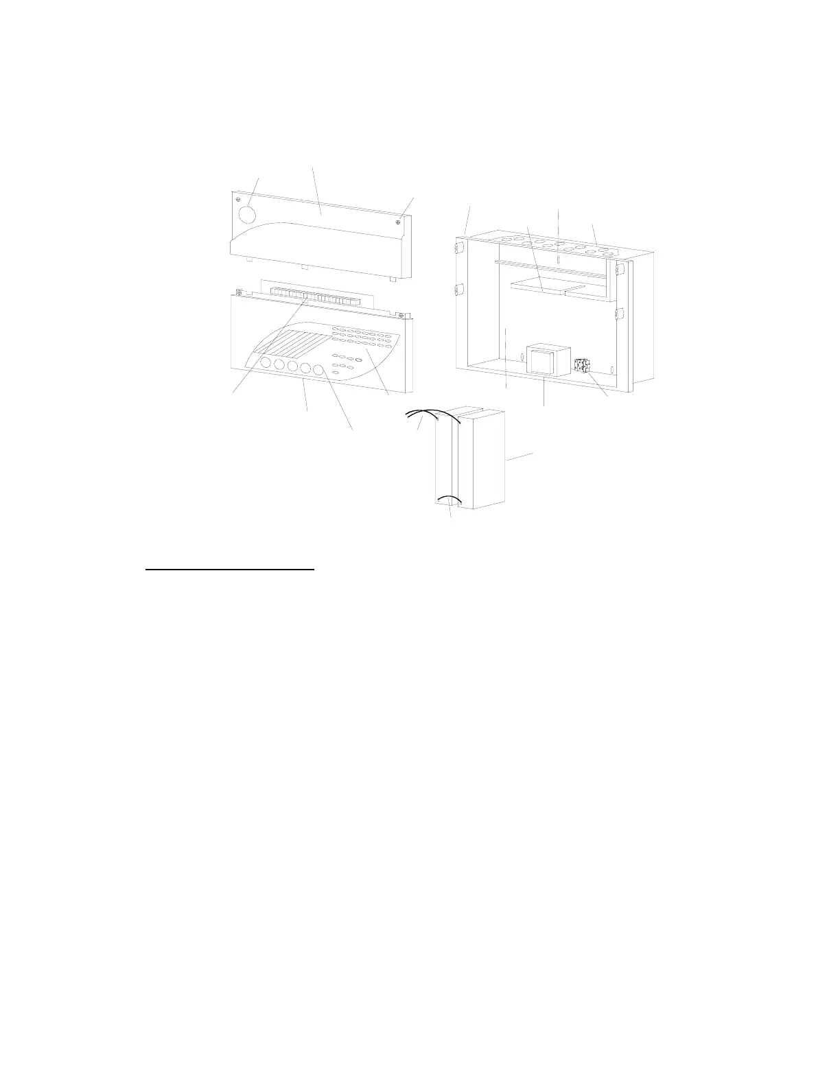
2.2.1 Mechanical Assembly Illustration
-
+
Battery leads
Red/Black
Battery link (Blue)
Fixing screws
Display cover
PCB terminals
LED indications
User controls
Terminal cover
Company logo
Transformer
Mains terminals
2 x 12v 2.1 Ah batteries
+
Battery space
-
Removable gland
plate with
protection plugs
PCB support
Pre-formed
Semi-flush
bezel
top fixing
Key hole
3. Panel Configuration
3.1 Buzzer Enable Link
The “Link for Buzzer Enable” link, located at the top right corner of the Control Board, is a
buzzer disable/enable facility. Its purpose is to disable the buzzer should this be helpful
during commissioning. DO NOT remove this link except in exceptional circumstances.
This link is not monitored by the control board and no faults or indications of any kind will
be generated if the link is removed.
3.2 Engineer’s Control:- 1-2 Zone Panels
This facility is located on the top right hand corner of the PCB. Its functions are described
below:
3.2.1 Processor Reset
Press to reset if the “Processor Fault” LED illuminates
3.2.2 One-man Test
If pressed for more than 5 seconds the panel will go into One-man Test mode.
3.2.3 Zone 1 Non-latch
Setting the zone 1 non-latch DIL switch to the ON position causes zone 1 to operate
in a non-latching fire indication mode. In this mode, if a fire condition occurs on zone
1 the panel will indicate the fire condition and operate the alarms. The auxiliary fire
www.acornfiresecurity.com