Component Testing Procedures
To avoid risk of electrical shock, personal injury or death; disconnect power to oven and discharge capacitor
before servicing, unless testing requires power.
October 2014 16500055
©2014 ACP, Inc.
Discharge Capacitor!
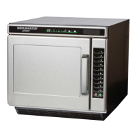
Remove all wires from terminals.
Measure resistance from:
230 to COM………………………………….
208 to COM………………………………….
230 to Ground………………………………..
208 to Ground………………………………..
Terminal 5 to 6……………………………….
Terminal 7 to 8……………………………….
Terminal 4 to Ground………………………..
< 2 Ω
< 2 Ω
Infinite Ω
Infinite Ω
< 1 Ω
< 1 Ω
Approximately 28 Ω
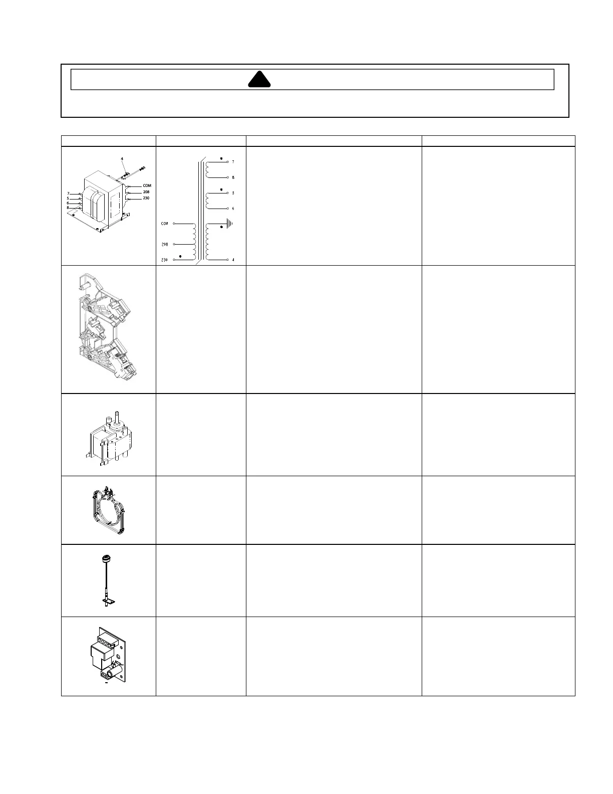
Interlock switch
Top = Primary 2-3
Middle = Monitor 7-8
Bottom = Secondary 4-5
Disconnect wires to switch.
Door OPEN measure resistance from:
Terminal 2 to 3
Terminal 7 to 8
Terminal 4 to 5
Door CLOSED measure resistance from:
Terminal 2 to 3
Terminal 7 to 8
Terminal 4 to 5
Open - Infinite Ω
Open - Infinite Ω
Open - Infinite Ω
Continuity - 0Ω
Continuity - 0Ω
Continuity - 0Ω
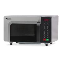
Remove all wires from motor.
Measure resistance between:
Orange/Blue and Brown terminals ..............
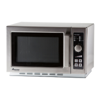
Disconnect wires from terminals.
Measure resistance across heater
Temp Sensor - RTD
(Resistance
Thermal Device)
Temperature
0° C (32° F) .................................................
24° C (75° F) ...............................................
177° C (350° F)............................................
Resistance
1000 Ω
1091 Ω
1654 Ω
With power applied, disconnect the J2
connector.
With door closed measure resistance from:
Pin 1 to pin 4 on J2 connector………………
With door open measure resistance from:
Pin 1 to pin 4 on J2 connector…..................
Open - Infinite Ω
Continuity - 0Ω