Component Testing Procedures
To avoid risk of electrical shock, personal injury or death; disconnect power to oven and discharge capacitor
before servicing, unless testing requires power.
16500055 October 2014
©2014 ACP, Inc.
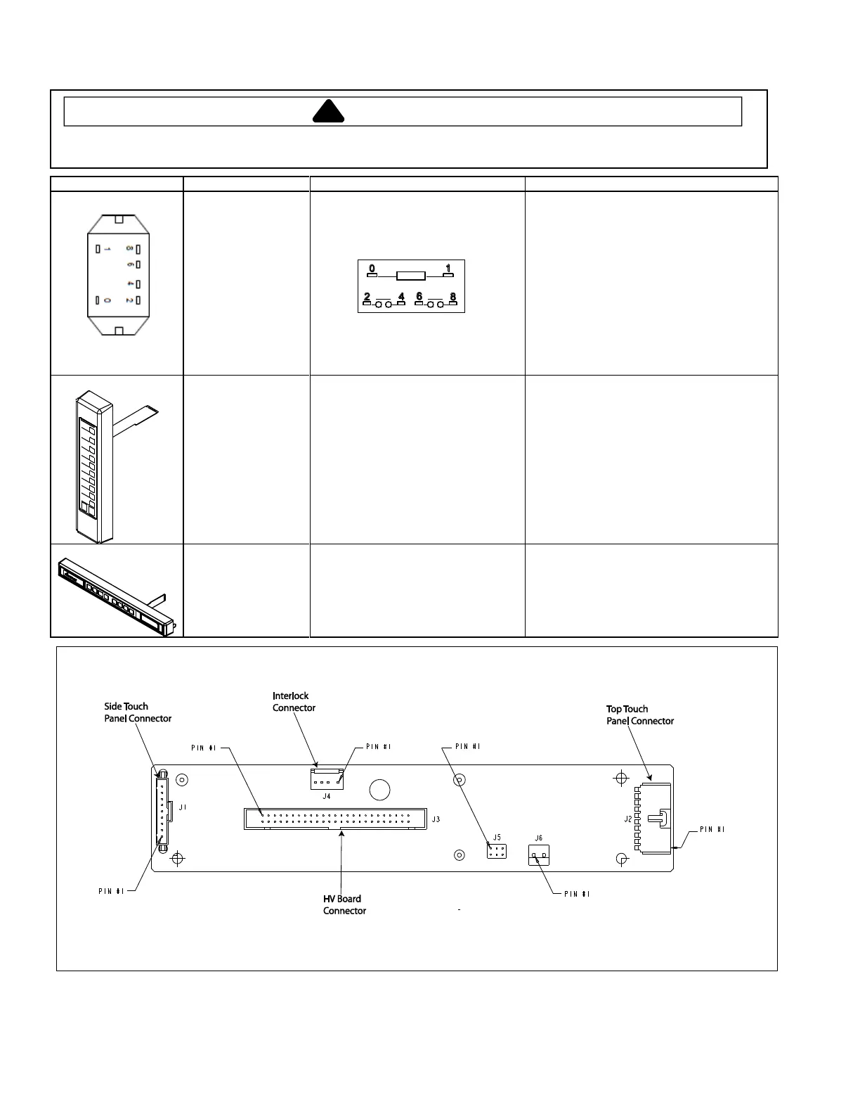
Measure resistance from:
Terminal 0 to Terminal 1 (coil) ............
Approximately 6 to 7 MΩ (Diode in circuit)
Note: If using a digital meter it must contain a
battery of 6 volts minimum.
WITHOUT line voltage applied to Terminals 0
and 1:
Contacts 2 -4 indicate Open – Infinite Ω
Contacts 6 -8 indicate Open – Infinite Ω
WITH line voltage applied to Terminals 0 and 1:
Contacts 2 -4 indicate Continuity – 0Ω
Contacts 6 -8 indicate Continuity – 0Ω
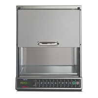
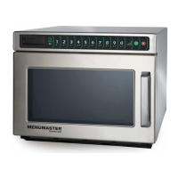
Select Time Entry on Top Touch
Panel and press each number pad to
ensure proper operation.
Inspect for any damage
Each number should operate with equal
force. If no response, unplug the Top Touch
Panel and test each pad again without
selecting Time Entry. If still no response,
replace the Side Touch Panel. If Side Touch
Panel operates properly with Top Touch
Panel disconnected, replace Tope Touch
Panel.
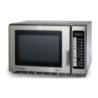
Press each pad (including Hidden
Pad – see Service Mode) to ensure
proper operation.
Inspect for any damage
Each pad should operate with equal force. If
no response, unplug the Side Touch Panel
and test again. Each pad should respond. If
still no response, replace Top Touch Panel.
Display Board – Connector Locations