`
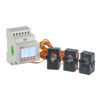
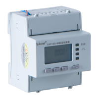
Installation method of open and close type mutual induction
Direction of
current
Positive pole(red)
Negative
pole(white)
Roche coil mounting method
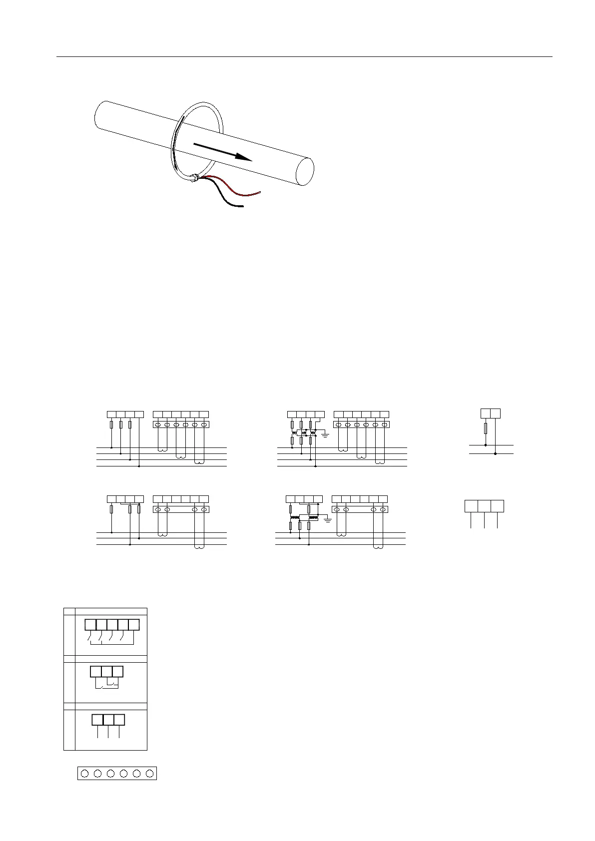
5.4Method of connection
(Note:in case of any inconsistency with the wiring diagram on the meter housing,the wiring diagram
on the meter housing shall prevail)
According to different design requirements,it is recommended to add fuses in the power supply and voltage input
terminals to meet the safety requirements of relevant electrical codes
A
B
C
N
U A U B U C U N I A
*
I A I B
*
I B I C
*
I C
F U S E S
A
B
C
N
U A U B U C U N I A
*
I A I B
*
I B I C
*
I C
F U S E S
A
B
C
U A U B U C U N I A
*
I A I B
*
I B I C
*
I C
F U S E S
A
B
C
U A U B U C U N I A
*
I A I B
*
I B I C
*
I C
F U S E S
3 - p h a s e , 4 - w i r e 3 C T
3 - p h a s e , 4 - w i r e 3 P T 、 3 C T
3 - p h a s e , 3 - w i r e 2 C T 3 - p h a s e , 4 - w i r e 2 P T 、 2 C T
S 1 S 2
S 1 S 2
S 1 S 2
S 1 S 2
S 1 S 2
S 1 S 2
S 1 S 2
S 1 S 2
S 1 S 2
S 1 S 2
* * * * * *
* * ** * *
*
*
*
*
*
*
*
*
*
*
5 6 7 8 9 1 0
1
2 3 4
5 6 7 8 9 1 01 2 3 4
5 6 7 8 9 1 0
1
2 3 4
5 6 7 8 9 1 01 2 3 4
24 25
Switch input (4DI)
26
DI1
DI2
A
A1
B
C
B1
34 35
Switch output(2DO)
36
DO1
DO2
C1
17 18
Ep
+
19
Eq
+
E-
2 pulse (2EP)
27 28
DI3
DI4
It is a test terminal for CT secondary side short coonnection.
 Loading...