Table 8
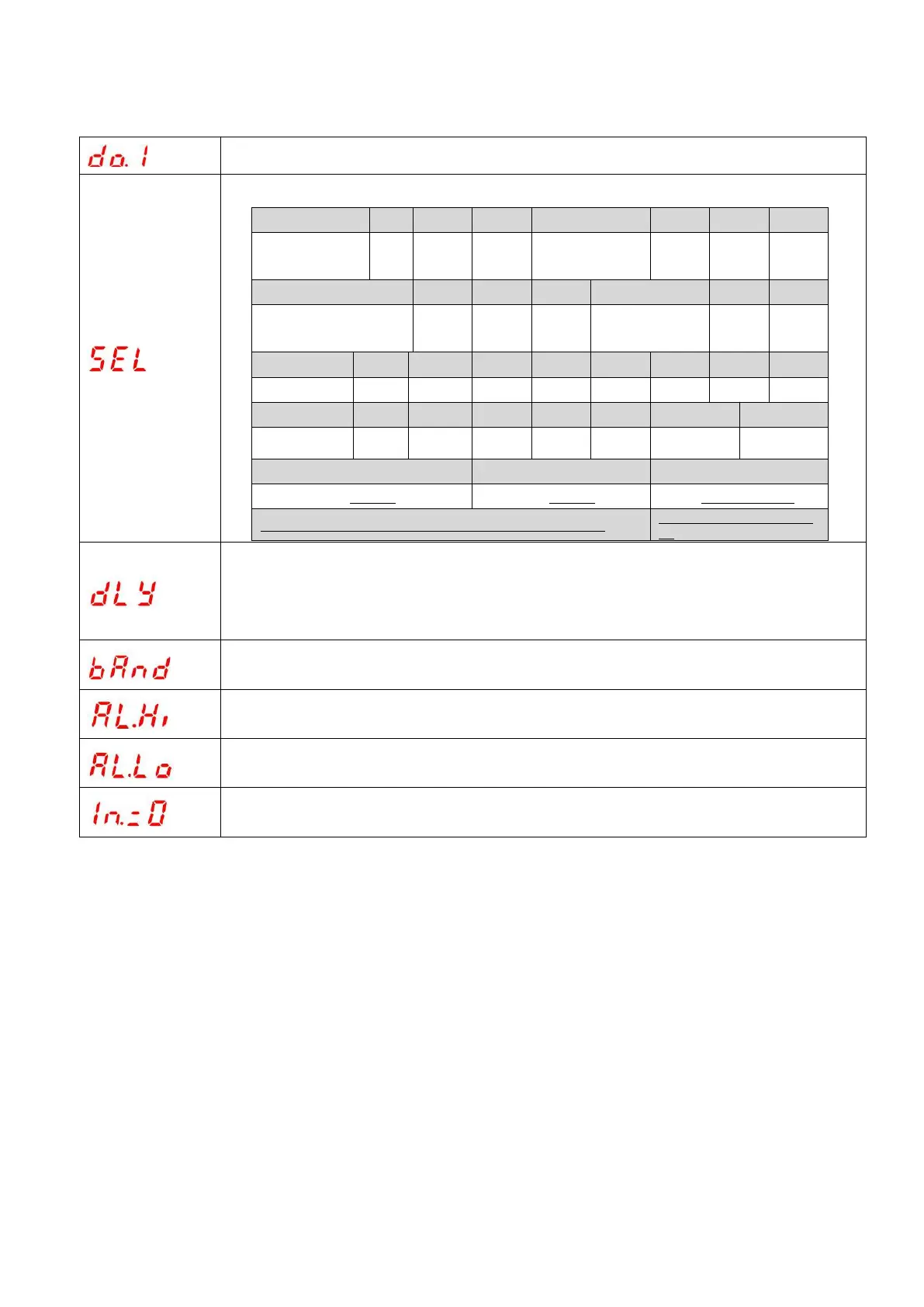
The first switching/relay alarm output
Three-phase
phase voltage
maximum value
hree-phase line voltage
maximum value
Three-phase
current maximum
value
The corresponding channel "In.=0" needs to be set to "Lo.on"
The second way DO can be
set
When the alarm item SEL is 00 (remote control), DLY indicates the duration after the switching
amount is activated.
When the alarm item SEL is not 00 (alarm), DLY indicates the delay time before the switching
action.
High alarm value setting (do not set the maximum 9999)
Low alarm value setting (do not set minimum -9999)
Whether low alarm is allowed when the signal is 0, Lo.on is enabled, Lo.of is forbidden
Note:
1. Hysteresis setting, high alarm value setting and low alarm value setting correspond to the display value of
the battery, and the display contains a decimal point.e.g. input 220V 100A/5A, three phase four wire, 100% P total
as 220*100*3=66kW, e.g. 100% power high alarm, "AL.Hi" taken as 66.00; 100% voltage high alarm, "AL.Hi"
taken as 220.0; 100% current high alarm, "AL.Hi" taken as 100.0
2.Indication of three phase XX maximum/minimum value: high alarm represents maximum value of three
phase; low alarm represents minimum value of three phase
3.Secondary DO to be set as "34.FL" combination alarm function; after setting, level II menu changed as
"SEL" (function selection), "dLy" (delay), "H-U" (high voltage), "L-U" (low voltage), "H-F" (high frequency),
"L-F" (low frequency), "H-P" (high frequency), "L-P" (low frequency), "H-I" (high current), "L-PF" (low power
factor), " H-b.U " (over voltage unbalance, set as -1 phase miss, judgment condition at least one phase>0.5Ue, at
least one phase<0.1Ue), " H-b.I " (over current unbalance, set as -1 phase miss, judgment condition at least one
phase>0.2Ie, at least one phase<0.01Ie).

 Loading...