8
protocol, various data information can be transmitted on the communication line.
Theoretically, up to 128 power meters can be connected simultaneously on a single line. Communication
address of each power meter can be set. When wiring, keep communication lines away from power cables or other strong
electric-magnetic field
6.4 supply voltage
The conventional power supply voltage of the instrument:AC/DC 85-265V;supply voltage with P2 funcion:AC/DC 115-415V.
7. Operation instructions
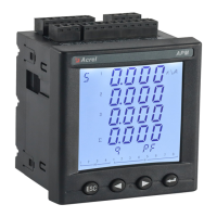
7.1 Display description
APM series uses LCD segment LCD display, the following table shows the segment codes for different characters.
A b c d E F
g
H
i / I
J K L M
n o
P
q
t U v W X y Z -
r
S
-
=
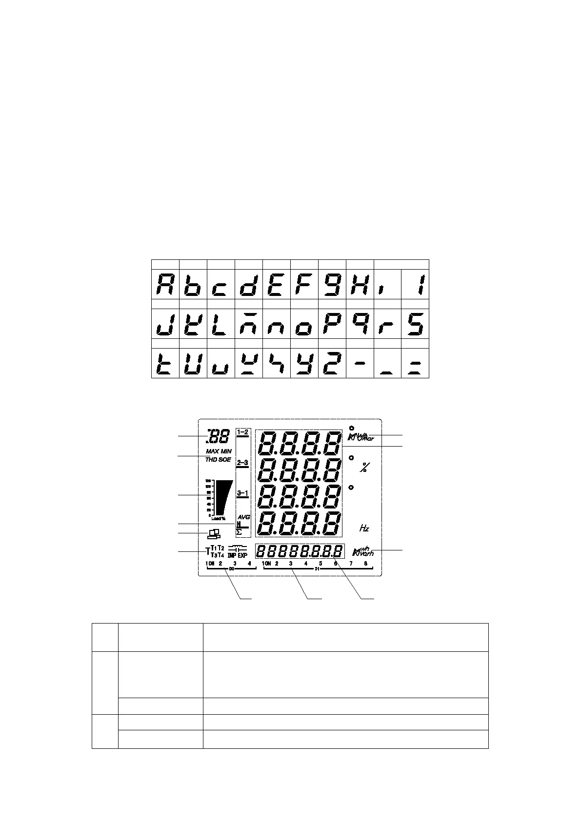
The following figure shows the screen when all character fields and indications are all lit.
The following table is a description of all the measurement and indication.
Identify what is displayed in the current measurement data display area 8:
Current / Voltage / Active Power / Reactive Power / Apparent Power / Power
Factor / Demand
DI, DO, AI, AO status/alarm log/TF card status
Records of maximum / minimum
Total harmonic distortion
 Loading...