4
4. Installation and wiring instructions
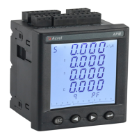
4.1 Installation dimensions
Meter and panel opening size(unit: mm(in))
Note: The maximum clamshell Angle is 90°.
Multiple meter installation (unit: mm(in))
4.2 Wiring method
According to different design requirements, it is recommended to add a fuse (BS88 2A gG) to the power supply and voltage input
terminals to meet the safety requirements of the relevant electrical specifications.
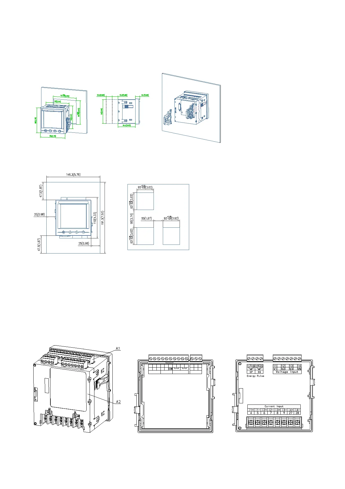
4.2.1 Main part
Terminal diagram: "4,5,6,7,8,9" is the current signal input terminal number; "11,12,13,14" the voltage signal input terminal number;
"1, 2" is the meter auxiliary power terminal number. "21, 22" is the communication terminal number; "17, 18, 19, 20" is the energy pulse
output terminal number; "30, 31, 39" is the switch input terminal number; "40, 41, 42, 43 " is the relay output terminal number. (Figure
1)
21 22
30
23 31 39 2
40
41 42 43 1
A1
DI1
B1
DI2
L/+
N/-
AUX Power
DO
DI
RS485
R1 R2
(Figure 1) (A1)Auxiliary power supply, etc (A2)Input of voltage and current