4
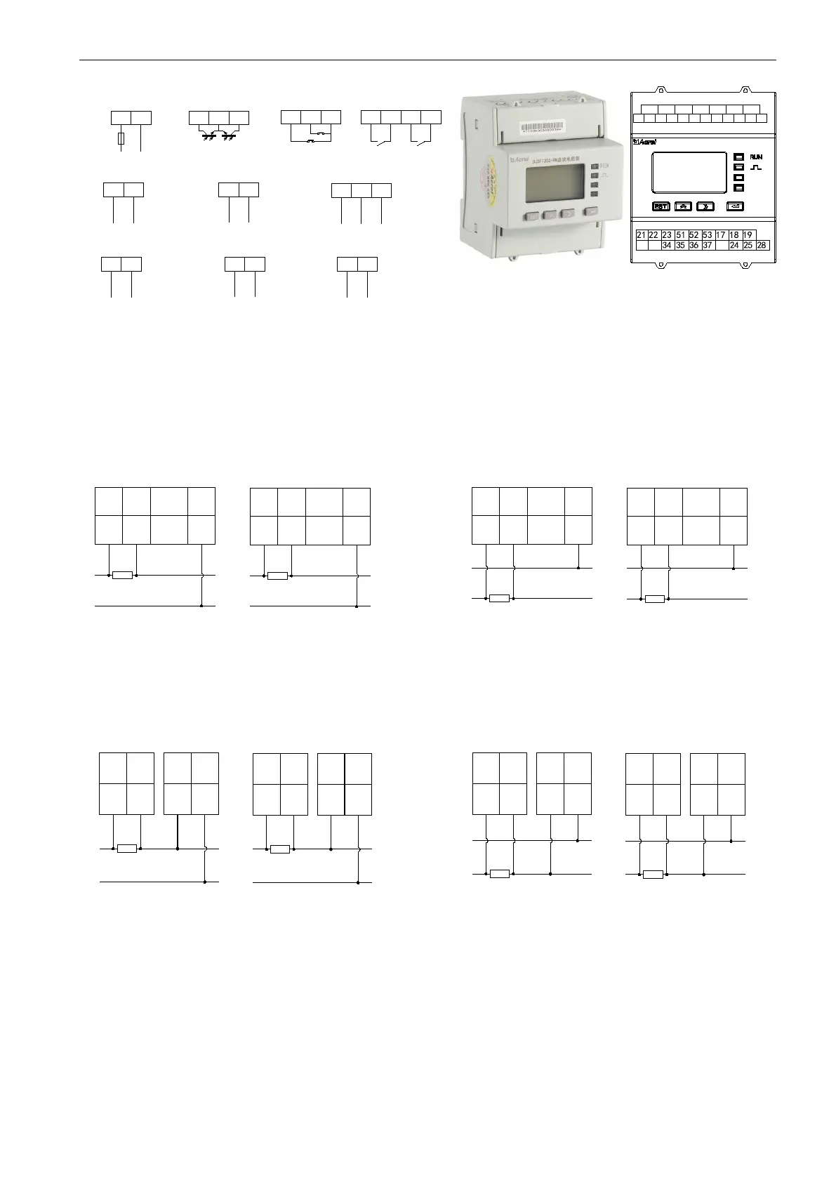
4.2 端子及接线 Terminals and wiring
1 2
F u s e
R S 4 8 5 通 讯
R S 4 8 5 C o m m u n i c a t i o n
L ( + )
辅 助 电 源
P o w e r
2 4
2 5
开 关 量 输 入
S w it c h i n g i n p u t
D I 1
D I 2
3 4
3 5
继 电 器 输 出
R e la y o u tp u t
C O M 2
2 8
脉 冲 输 出
P u ls e o u t p u t
3 6
3 7
1 7 1 8 1 9
2 1 2 2 2 3
N ( - )
E P +
C O M
T P +
A
B
C O M 1
D 0 1
D 0 2
第 二 路 通 讯
S e c o n d c o m m u n i c a t i o n
6 0 6 1
A 2
B 2
第 二 路 电 流 输 入
S e c o n d c u r r e n t i n p u t
6
7
I 2 +
I 2 -
第 二 路 电 压 输 入
S e c o n d v o l t a g e i n p u t
1 3 1 4
U 2 +
U 2 -
第 一 路 电 流 输 入
F i r s t c u r r e n t i n p u t
4
5
I 1 +
I 1 -
第 一 路 电 压 输 入
F i r s t v o l t a g e i n p u t
1 1 1 2
U 1 +
U 1 -
注:第二路直流输入以及DI、DO功能均为选配功能。
Note: The second DC input channel and DI and DO
functions are optional.
When the current input mode is current shunt input:
三线制接法Three-wire connection
正极电流分流器输入 负极电流分流器输入
Current shunt connected to the positive Current shunt connected to the negative
4 5
+
-
xxxA/75mV
12
Load
6 7
+
-
xxxA/75mV
14
Load
I1+
I1-
U1-
I2+
I2-
U2-
4 5
+
-
xxxA/75mV
12
Load
6 7
14
I1+
I1-
U1-
I2+
I2-
U2-
+
-
xxxA/75mV
Load
第一路直流输入 First DC input channel 第二路直流输入Second DC input channel
四线制接法Four-wire connection
正极电流分流器输入 负极电流分流器输入
Current shunt connected to the positive Current shunt connected to the negative
+
+
-
xxxA/75mV
-
4 5
1211
+
-
515253
+
-
负载
第一路
+
+
-
xxxA/75mV
-
负载
第二路
6 7
1413
电流为霍尔传感器输入时:
I1+
I1-
U1+
U1-
+12V
-12V
G
I2+
I2-
U2+
U2-
+12V
-12V
G
+
-
+
-
+
-
xxxA/75mV
负载
第一路
第二路
+
-
xxxA/75mV
负载
外置电源模块
正极电流分流器输入
4 5
+
+
-
xxxA/75mV
-
12
Load
第一路
6 7
+
+
-
xxxA/75mV
-
14
Load
第二路
I1+
I1-
U1-
I2+
I2-
U2-
负极电流分流器输入
4 5
+
-
xxxA/75mV
12
Load
第一路
6 7
14
第二路
I1+
I1-
U1-
I2+
I2-
U2-
+
-
xxxA/75mV
Load
四线制接法:
11
U1+
13
U2+
13
U2+
11
U1+
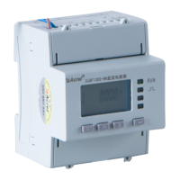
DJSF1352-RN直流电能表
2 1 12 11 5 4
14 13 7 6