Ultrasonic flaw detector А1212 MASTER
Operation Manual
31
ACOUSTIC
CONTROL
SYSTEMS
2
The following parameters are used for calculations as well: OPERATIONAL FREQUENCY, ANGLE OF INCIDENT, DELAY, and
ULTRASONIC VELOCITY. If some parameter used for calculation of the DGS diagram changes, then the diagram will be auto-
matically recalculated.
Functions of the keys applicable for DGS adjustment are presented in the Table 12.
Key Description
Adjustment of gain (amplification)
Move the strobe to the le/right
Changes the length of the strobe with reference to its le boundary
Exits the DGS settings mode
Opens a confirmation window of new DGS settings
Table 12
Figure 25
Table 13
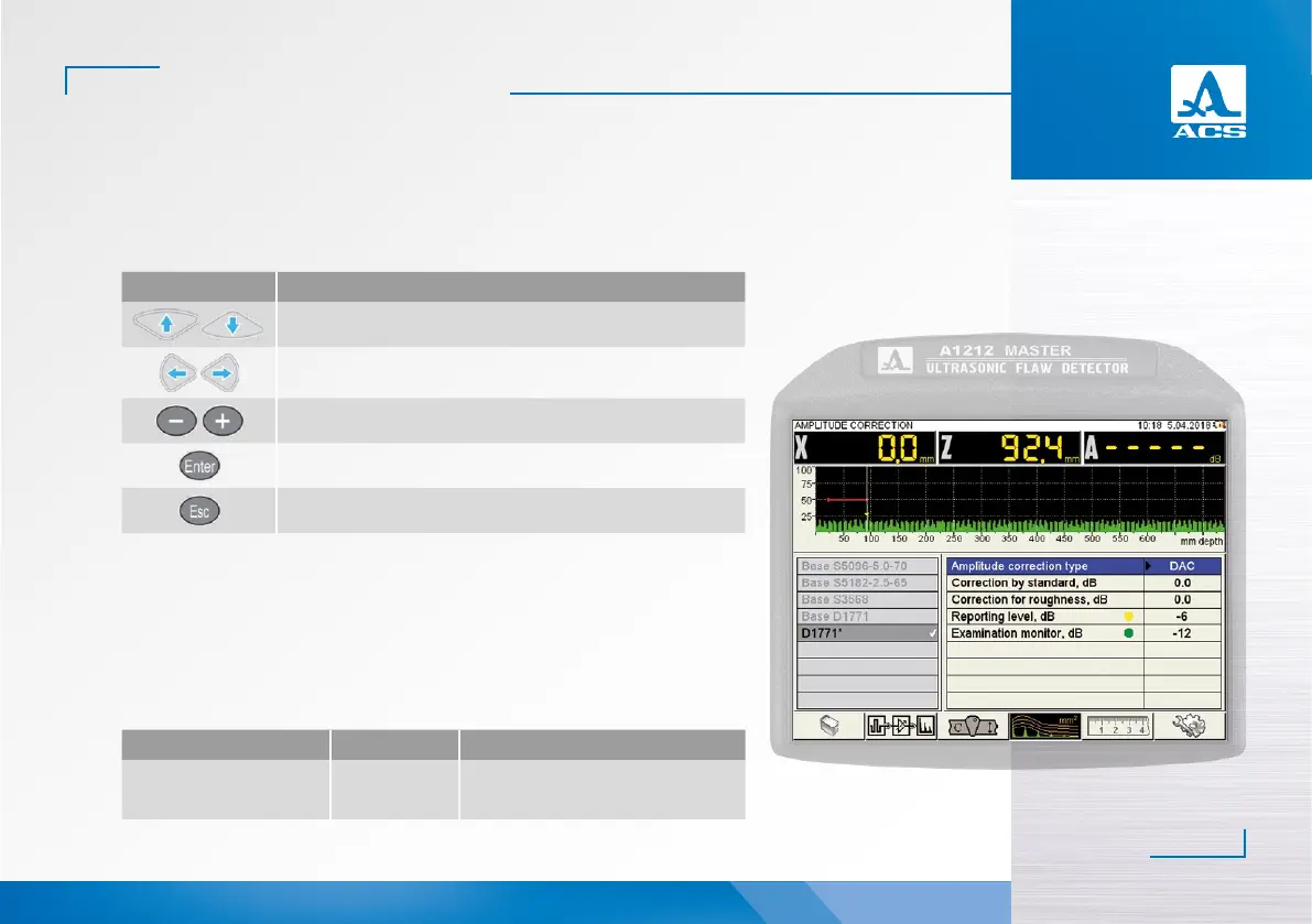
2.3.1.4.3 Adjustment of the amplitude correction – DAC
The DAC curve is used to adjust the sensitivity and estimate the size of the flaws by the
amplitude.
The screen when setting the DAC parameters is presented in the Figure 25.
The names of the DAC parameters and their permissible values are presented in the Table 13.
Parameter name Value Description
Type of amplitude correction DAC
DAC was selected in the function of
amplitude correction
▼
 Loading...