Ultrasonic flaw detector А1212 MASTER
Operation Manual
8
ACOUSTIC
CONTROL
SYSTEMS
1.3.1 Design
The flaw detector includes an electronic unit to which the removable piezoelectric transducers (PTs) are connected via cables.
1.3 DESIGN AND OPERATION
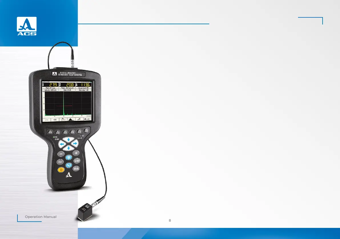
Figure 1
1
1.3.1.1 Electronic unit
The electronic unit provides the generation of electrical impulses for excitation of the piezoelectric transducer,
amplification of the signals received from the PT. The electronic unit generates and processes measurement results
and provides their display in digitalized form, records data into nonvolatile instrument’s memory and allows their
transfer to the external PC.
The external design of the electronic unit is presented in the Figure 1.
The instrument is controlled by means of a membrane keyboard. The display and LEDs on the housing of the
device indicate the signals, measurement results and state of the instrument.
The PT is connected via coaxial cables (included in the delivery kit) by means of the LEMO connectors.
The instrument is powered from the battery unit or a power adaptor included in the delivery kit.
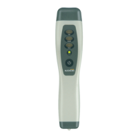
1.3.1.2 Power adapter
The power adapter provides external power supply of the instrument and charging of the battery unit from AC
mains (15 V).
The charge time depends on the depletion of the accumulator unit; it can last up to 3 hours. The instrument can
be operated during charging of the battery.
Always connect the cable of the power adapter to the electronic unit first, then connect the network cable to the
power adapter, and then connect the network cable to the AC mains to prevent damage of the instrument.
1.3.2 Transducers
The flaw detector is designed to operate with single crystal and double-crystal PTs with operating frequencies
from 0.5 to 15.0 MHz.