Ultrasonic flaw detector А1212 MASTER
Operation Manual
47
ACOUSTIC
CONTROL
SYSTEMS
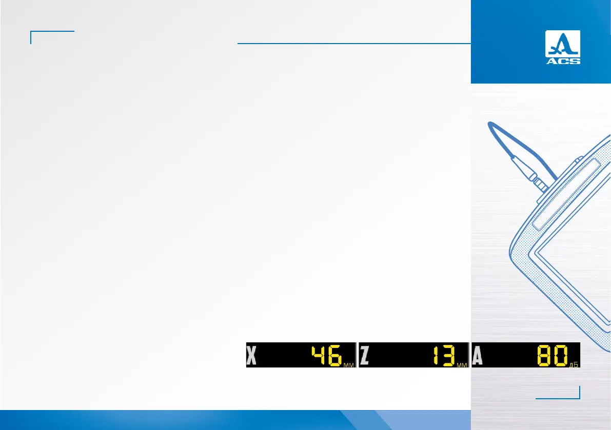
The following is displayed in the operating mode:
- in the first block: distance from the front edge of the PT to the reflector on the surface of the object under inspection;
- in the second block: depth of location of the fault. If the angle beam PT is used and when the thickness value of the
object under inspection is entered (see Chapter 0) a real fault location depth will be displayed considering the rereflections of
the ultrasonic wave;
- in the third block: amplitude of the signal being measured.
In the area of auxiliary quantities the following parameters are displayed:
- Length, mm is the distance from the beam index of the PT to the reflector by the central beam.
- Thickness, mm is the thickness value of the object under inspection and the quantity of rereflections of the central beam.
It shall be set in the SETTING mode for the angle beam PTs.
- Acceptance level is a value of the acceptance level calculated automatically in the SETTINGS mode. If DGS is On this filed
displays the “Equivalent area” parameter is a value of acceptance equivalent area of the flat-bottomed hole.
- Velocity, m/s is the velocity value of the ultrasonic wave, set in the SETTING mode.
- Gain, dB is the amplification value, set in the SETTING mode.
- Gain step, dB is the switching step of the amplifier, selected in the SETTING mode.
In the area of A Scan besides the A Scan the following is displayed: a grid, vertical and horizontal scale, strobes, if switched
On, the cursor and the marker. The soware renews the cursor and the marker when the measurement results are renewed.
The horizontal scale of the instrument toggles between microseconds and millimeters.
The icon area is located below. Each icon is controlled by the corresponding key on the panel. The main functions of the
keys and corresponding icons in the FLAW DETECTOR mode:
- F1 control the first strobe;
- F2 control the second strobe;
- F3 selection of the AFAS actuation type;
- F4 selection of the form of the displayed signal;
- F5 switch On/Off the LOOP mode;
- F6 switch On/Off the amplitude correction.
Figure 49
2