Ultrasonic flaw detector А1212 MASTER
Operation Manual
50
ACOUSTIC
CONTROL
SYSTEMS
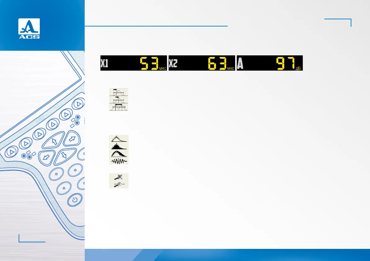
In the panel of the measurement results in the first block is start of the strobe (X1), in the second block it is the end of the
strobe (X2), in the third block it is the level of the strobe (A) (Figure 50).
Figure 50
F3 (Actuation type)
Selecting the type of AFAS actuation:
- by first signal excess over the level of the strobe for the first time;
- by the signal peak value in the strobe;
- between the peak values (maximums) of the signals in the strobes (if both strobes are On).
In the measurement mode to the maximum the positions of the cursor and the marker coincide.
F4 (Form of the signal)
Switching between the signal forms in the A Scan area:
- detected contoured;
- detected shaded;
- dimensional envelope (except the LOOP mode);
- radiofrequency signal (except the DAC mode).
F5 (Loop)
- LOOP mode is Off;
- LOOP mode is On.
If the LOOP mode is ON, then two images of the signal are simultaneously displayed on the screen.
Prior to switching On the LOOP mode, always switch On the first strobe. Aer the mode is switched On, the upper graphical
window will display an A Scan with the strobes, and the lower window will display an extended time interval corresponding to
the first strobe. The presence of the lower window allows detailed estimation of the form of the part of the signal time realiza-
tion within the limits of the first strobe.
The display in the LOOP mode is presented in the Figure 51.
2
 Loading...