ACT 10 Digital Keypad Operating & Installation Instructions
6
Incorrect Code Lockout When three invalid codes have been entered in a row, the keypad will enter
lockout mode for 20 seconds. During this time, the red LED indicator will flash and all PIN codes will be inactive.
Restoring Factory Defaults
Enter Programming Mode followed by . This restores the ACT 10 Digtal Keypad to its default
settings. If the Programming Code has been forgotten, it may be set to 9999 by:
1. Remove the power from the unit. 4. Replace link LK1.
2. Remove link LK1 at the back of the unit. 5. Proceed with programming.
3. Apply power to unit.
Note: The keypad will not operate correctly without LK1 in place.
!
OM
R O
N
5A
25 0 V
A C
5A
30 V
DC
0123456789
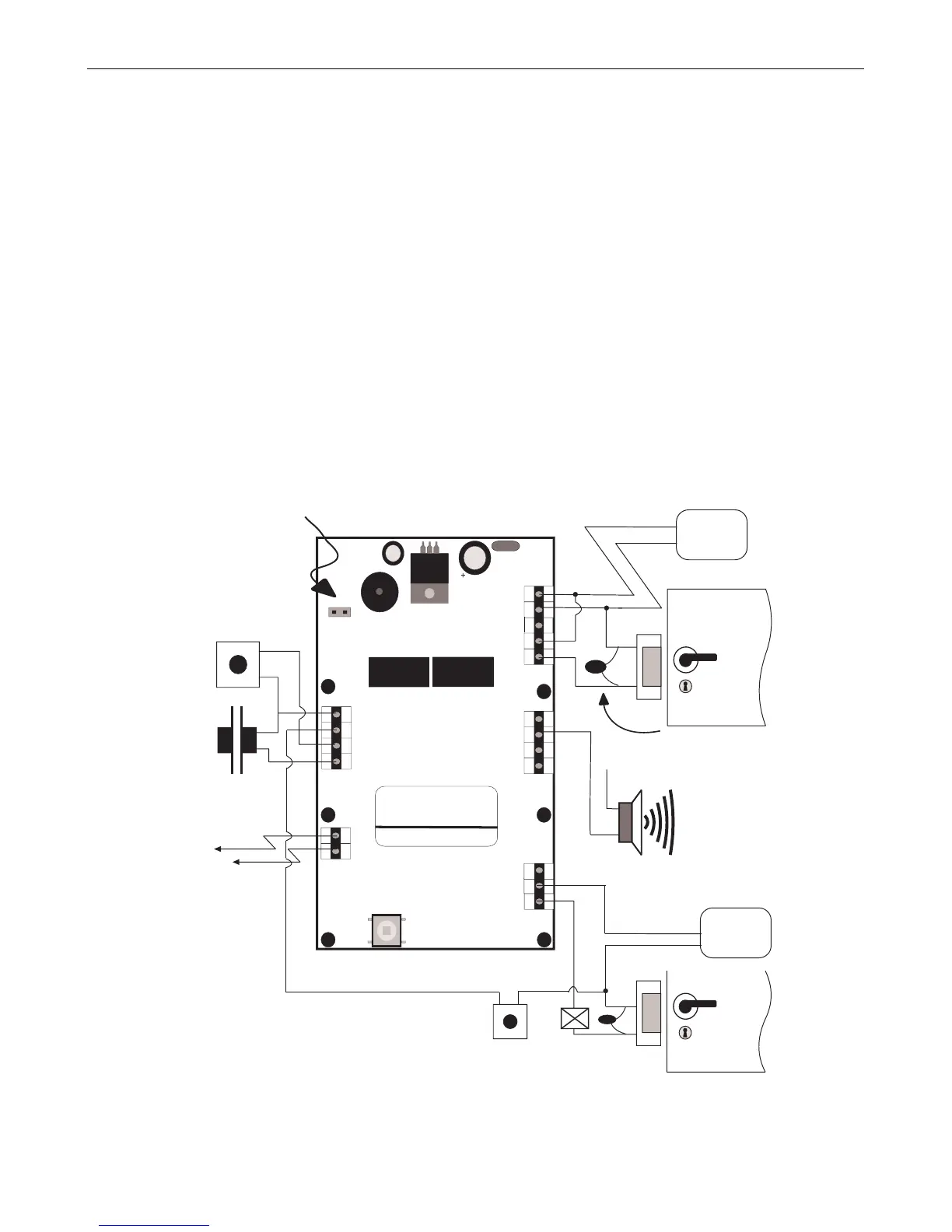
Important
Always Place Varistor
Across All Lock Terminals
+V
+V
0V
Volt - Free
Tamper Contacts
Door Contact
Door Release
Button
Guest Buzzer
Output sink = 100mA max
Power Supply
12-24V ACDC
12-24
AC/DC
-
+
N/C
N/O
C
0V
Buzzer
OP3
Duress
OP2
Interlock
OUTPUTS
INPUTS
0V
Interlock
(PB2)
Push
Door
Contact
Button
TAMPER
LK1
Serial No. 12345
Batch: 20xx-1
Product:ACT10 Rev3.0
N/C
N/O
C
+V
0V
Door Release Button
for Door 2
RELAY
DOOR 2
OM
R O
N
5A
25 0 V
A C
5A
30 V
DC
Door 2
12-24V ACDC
Power Supply
Shows connection for normally
energised lock, (e.g. magnetic lock).
Shows connection for normally
DE-ENERGISED lock, (e.g. door-strike).
Break Glass
Unit (optional)
Power up without link if
Programming Code has
been lost
Shows connection for normally ENERGISED
lock (e.g. magnetic lock)
The ACT 10 may be used to control 2 doors as illustrated in the diagram above
Figure 1: Typical ACT 10 Configuration
!
OM
R O
N
5A
25 0 V
A C
5A
30 V
DC
0123456789
Important
Always Place Varistor
Across All Lock Terminals
+V
+V
0V
Volt - Free
Tamper Contacts
Door Contact
Door Release
Button
Guest Buzzer
Output sink = 100mA max
Power Supply
12-24V ACDC
12-24
AC/DC
-
+
N/C
N/O
C
0V
Buzzer
OP3
Duress
OP2
Interlock
OUTPUTS
INPUTS
0V
Interlock
(PB2)
Push
Door
Contact
Button
TAMPER
LK1
Serial No. 12345
Batch: 20xx-1
Product:ACT10 Rev3.0
N/C
N/O
C
+V
0V
Door Release Button
for Door 2
RELAY
DOOR 2
OM
R O
N
5A
25 0 V
A C
5A
30 V
DC
Door 2
12-24V ACDC
Power Supply
Shows connection for normally
DE-ENERGISED lock, (e.g. door-strike).
Break Glass
Unit (optional)
Power up without link if
Programming Code has
been lost
Shows connection for normally ENERGISED
lock (e.g. magnetic lock)
The ACT 10 may be used to control 2 doors as illustrated in the diagram above
Figure 1: Typical ACT 10 Configuration