ACTsmart2 Operating and Installation Manual Rev. 2
Copyright © 2015 Access Control Technology Ltd.
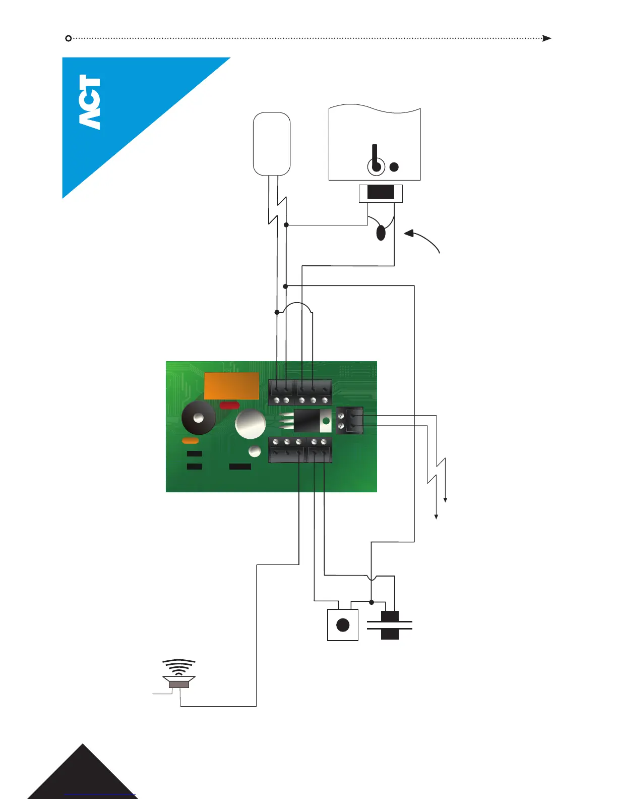
TAMP
1 2
12-
24V
0V
N/O
COM
N/C
B
A
AUX
I/O2
Prog I/P
Aux I/O1
LK 2
LK 1
© Copyright of Access Control Technology Ltd 2015
Training is available on all ACT products - email training@act.eu for more information
Door
Contact
Door Release Button
Tamper
This illustration shows wiring
for normally de-energised locks.
If normally energised locks are
required, use the N/C relay contact.
Important!
Always Place Varistor
Across Lock Terminals
Volt-Free
Tamper Contacts
+12V
0V
+V
The Aux I/O Output is an open
collector output capable of
sinking 100mAmps.
The ACTsmart2 may be powered
from 12 or 24V AC or DC for
Standalone operation.
ACTsmart2 Keypad - Installation Diagram
Default configuration for
AUX I/O 2 is Door Alarm.
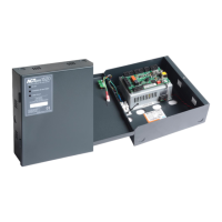
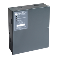
Power
Supply Unit
19