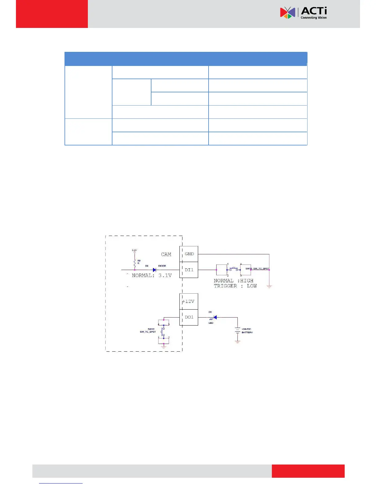
Typical Connection
Based on these specifications, if the DI device has a voltage of 0V ~ 30V or the DO device has
a voltage of < 24V (<100mA), then the camera can supply internal power to these devices and
there is no need to connect the DI/DO device to an external power source.
In this case, wire connection to Pins 1 to 4. Use the DIO GND and DI pins to connect a DI device
and use the DIO PW and DO pins to connect a DO device. See wiring scheme below:
High Voltage DO Device Connection
Even though the camera provides 12V power, this may not be enough for some high voltage
DO devices, such as a ceiling light or a motor that opens or closes a gate. In this case, there is
a need to connect an external relay. See wiring scheme below: