Hardware Manual
33
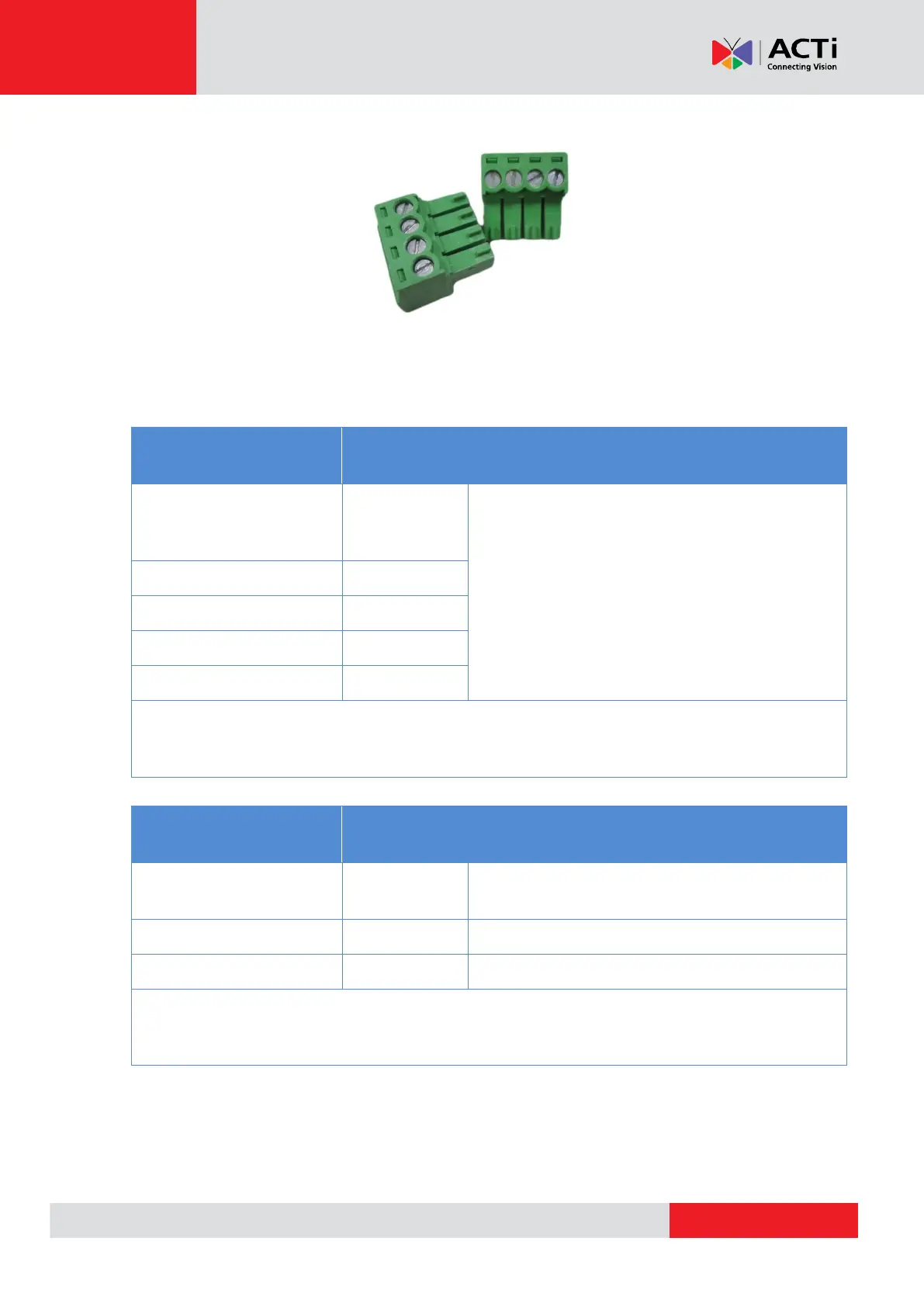
The camera comes with two (2) terminal blocks to connect DI/DO devices.
Map the pins according to one of the pin combinations on the table below. Loosen the screw and
insert the wire through the pin slot on the terminal block, then tighten the screw to secure the wire.
Connect the terminal block(s) to the corresponding cable connector(s).
To connect digital input devices, map the DI
device wires to the following:
NOTE: In case of connecting more than one DI device, the GND pin can be commonly
shared by all four (4) DI devices.
To connect digital output devices, map the
DO device wires to the following:
NOTE: In case of connecting two (2) DO devices, the 12V pin can be commonly
shared by the two (2) DO devices.