Installation and Commissioning Guide - Split Ducted ESP Plus/Ultima Indoor Unit
Doc. No.0525-078 Ver. 2 190925
10
Installation and Commissioning Guide
Split Ducted ESP Indoor Unit
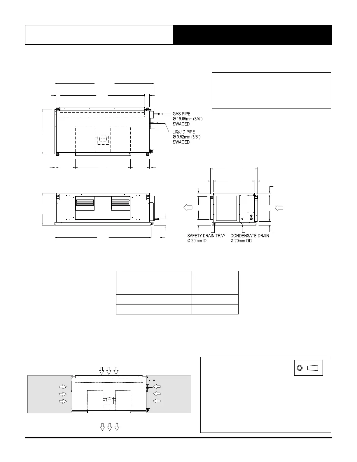
05.02. SRV151E / SRM151E SRV171E / SRM171E
MINIMUM SERVICE ACCESS AREAS AND AIRFLOW CLEARANCES
NOTES:
1. Do not scale drawing. All dimensions are in mm unless specified.
2. Refer to Field Pipe connection details on specifications sheet.
3. Service Clearances given are suggested minimum based on the
condition that the spaces around the units are free from any
obstructions and a walkway passage of 1000mm between the
units or between the unit and the outside perimeter is available.
4. Minimum service access clearances are responsibilities of the
installer, ActronAir will not be held liable for any extra charges
incurred due to lack of access.
THIRD ANGLE
PROJECTION
EC
ID FAN
EC
ID FAN
INDOOR COIL
HEIGHT CLEARANCE = 340mm
DUCT WORK
DUCT WORK
850 mm
SERVICE
CLEARANCE
850 mm
SERVICE
CLEARANCE
(ELECTRICALS)
RF
LFLR
RR
ELECT
BOX &
ACCESS
PANEL
1100
80
715
20
20
INDOOR COIL
412
O/A
615 O/A
1250
40
300
72
40
340
22
50
115
252.5 252.5
575
SUPPLY
AIR
RETURN
AIR
1290 O/A
40
535
70
50
EC
INDOOR
FAN
EC
INDOOR
FAN
SUPPLY AIR
TOP VIEW
FRONT VIEW
SIDE VIEW
OVERALL NOMINAL DIMENSION H X W X L
= 412 X 1290 X 615
SUPPLY DUCT H X W = 300 X 715
RETURN DUCT = 340 X 1100
CONDENSATE DRAIN CONNECTION = 20mm OD
UNIT MODEL NUMBER
UNIT WEIGHT
(kg)
SRV151E / SRM151E 61
SRV171E / SRM171E 62
ELECT
BOX AND
ACCESS
PANEL