11
A 2 0 0 0 - S E R I E S A M P L I F I E R U S E R G U I D E
©2012 Indy Audio Labs, LLC all rights reserved / Revision20120420
Document No. 1000571
Discovering the IP address with a Mobile Device:
On a mobile device such as an iPad or iPhone, down-
load one of several available IP address scanner
programs such as iNet or IP Scanner. Programs such as
these are typically free or available for sale for a nominal
fee. Similar Android and other mobile OS apps are
available with this capability. These programs scan the
entire network and list the connected devices, their IP
addresses and their MAC addresses.
IP Discovery via Traditional Computer: On a laptop or
desktop computer, login to the local router administration
software, open the list of attached devices and note the
assigned IP address of the amplier from the list of con-
nected devices on the local network.
Amplifier Control and Status using E2C
To illustrate how to control and monitor status of an
Acurus amplier using E2C, let’s assume you are operat-
ing on a DHCP-enabled network and have discovered
the amplier at IP address 192.168.1.125. You can now
connect to the amplier using your control computer
or mobile device by typing the above IP address in the
browser window.
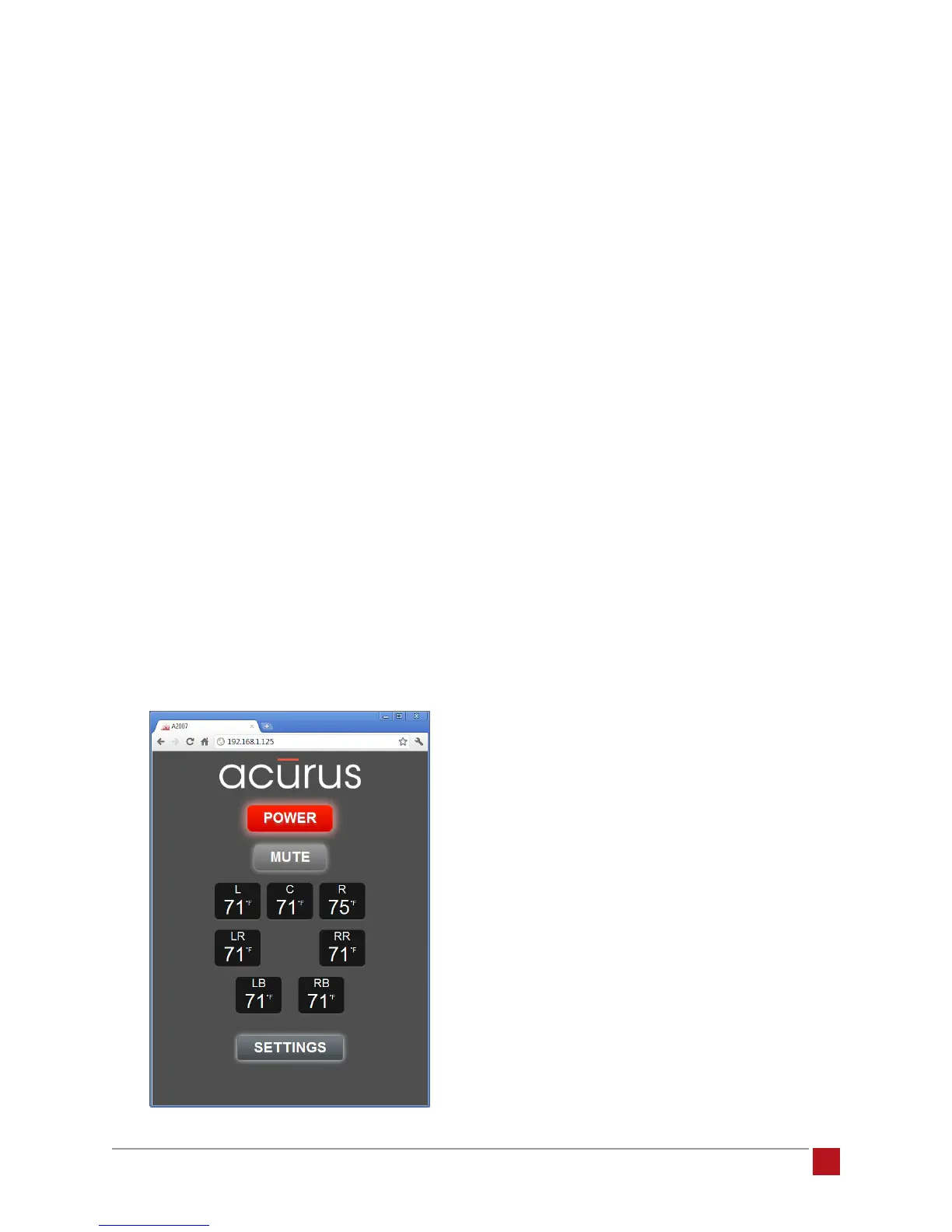
A view of the main control page similar to the one below
should appear (A2007 shown):
Power: This button performs the same function as the
front panel button on the amplier. The color of the but-
ton matches the light ring on the physical unit. It toggles
the unit between “on” and “standby” operation.
Mute: The mute button removes the audio output from
all channels of the amplier to the loudspeakers while
keeping the amplier channels powered on. In addi-
tion to providing a quick way to cut out audio in a room,
this feature is useful for breaking the signal path to help
diagnose possible sources of noise or other issues.
Channel Temperature Indicators: These indicators
provide real-time temperature information from each of
the channels. When in standby, or after initial power up,
these indicators will typically match room temperature
(within a few degrees). After several minutes of warm
up, when the channels have reached normal operating
temperature, these meters normally indicate channel
temperatures in the 95-110 degree F range. It is not unu-
sual to have up to 9 degrees of variation from channel-
to-channel. However, if one particular channel is running
outside this range, there may be an abnormal condition
such as a mismatch with a speaker load or service
adjustments that need to be made on the amplier by a
service technician. The number of Channel Temperature
Indicators in this view varies according to the number of
channels (2, 5 or 7) the amplier model provides.
Settings Button: The settings button opens the settings
page of the interface.