© ADB Airfield Solutions All Rights Reserved 27
2.3.4.1 ACE2 Cable Entry NOTE: All conduit and wiring must only enter the ACE2 enclosure through the bottom or
through the top access plate. This facilitates quick maintenance and replacement of the
ACE2 unit.
DO NOT blow out enclosures because metal shavings can damage the electronics.
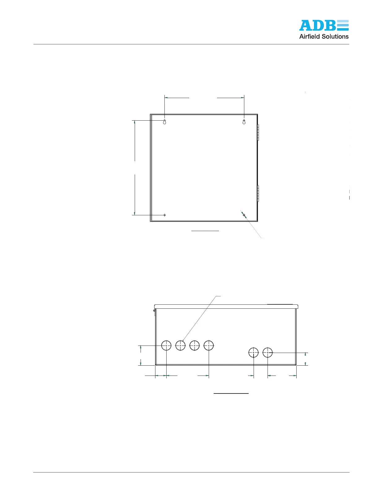
Figure 19: Combo Box-Mount, Interior Drawing
There are six knockouts each in the top and in the bottom of the enclosure walls for one inch
EMT metal conduit fittings for wires and fiber optic cables. See Figure 19 and Figure 20 for
dimensions in inches, and see Figure 22 for routing. Power and ACE-to-ACE communication
wiring must be in separate conduits.
Figure 20: Combo Box-Mount, Bottom View
∅.312-inch MOUNTING HOLE
4 PLACES
15.00/381
17.88
454
BACK VIEW
MOUNTING HOLE LOCATIONS
SECTI
SCALE
GND NEU HOT
ACE POWER
FROM 120V UPS
Dimensions
inch/mm
1.82/46
4.07
103
2.00
51
2.82/72
1.57/40 6.00/152
KNOCKOUT FOR 1" CONDUIT
(Ø 1.375 NOM)
BOTTOM VIEW
Dimensions
inch/mm