© ADB Airfield Solutions All Rights Reserved 37
2.6 Wiring Schematics This section provides wiring schematics for L-827/L-829 Advanced Control Equipment
(ACE2).
See Figure 30 for the L-827/L-829 ACE2 wiring connections to the constant current regulator
(CCR).
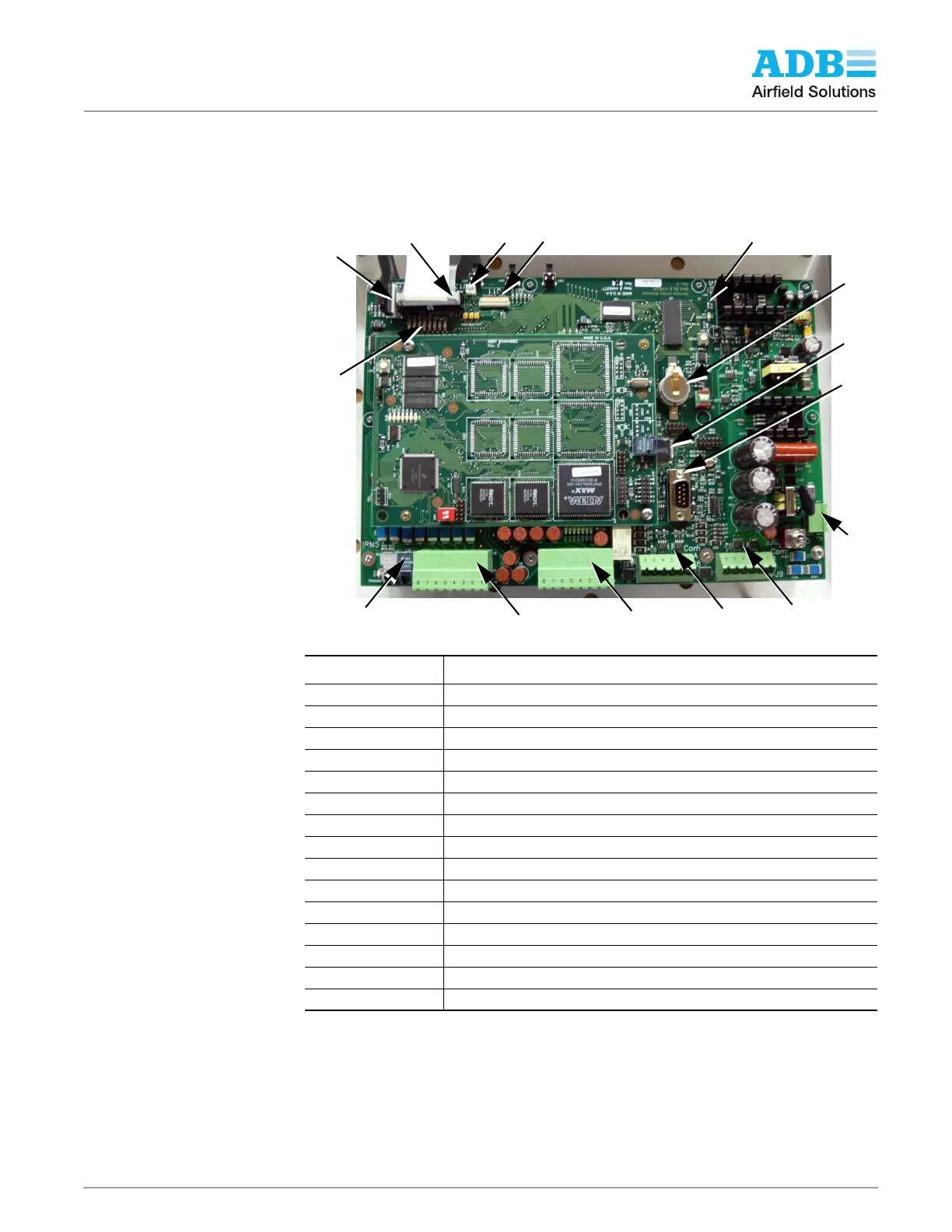
2.6.1 Connectors Figure 24: Internal Connections
NOTE: A. Terminal block J4 accepts any discrete contact closure that uses 24 to 250V AC/DC control voltage.
Examples of useful inputs are: CCR Over Current, CCR Over Voltage, CCR Primary Power, CCR Remote Local,
CCR Open Circuit, CCR Access Door open, etc.
NOTE: B. Terminal block J5 carries system latching relay outputs that are used to control brightness steps of a
CCR. These outputs can also be configured to control any element that requires an ON/OFF contact closure. The
output current is 1A max so 20 AWG wire or larger is suggested. In addition, these terminal blocks can be
configured to control both CCR brightness steps and a L-847 Circuit Selector Switch.
Table 10: Main Board Connectors
Function Description
J1 Input Power
J4 Discreet Input (See Note A)
J5 Discreet Output (See Note B)
J8 Com A RS-422
J9 Com B RS-422
J10 LCD Board Ribbon Cable Connector
J11 LCD Connection Ribbon Cable Connector
J12 External Keypad Connection
J13 ACE2 External Display Power
J14 Configuration Port RS-232
U6 Non-Volatile Memory
U21 CVM Fiber Optic Port
D1 Internal Power Present LED
D7 thru D15 Internal Status LEDs
IRMS IRMS Fiber Optic Interface Connection
J1
J5
J9
J8
J4
IRMS
J14
U21
U6
J10
J3
J11
D1
J12
D7-D15