welcome contents
installation
&operation
special
configuration
furter
information
6
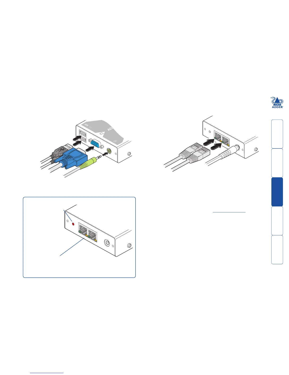
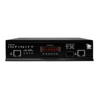
Connections at the X200 (remote) module
1 Place the X200 module adjacent to the remote user location.
2 Attach the video monitor, USB keyboard, USB mouse and speaker
connectors to the sockets of the Adder X200 module.
3 Attach the connector of each cable run leading from the CAMs (and/or
AdderView CATx switch) to the TO LOCAL 1 and TO LOCAL 2 sockets of the
X200.
From USB
mouse and
keyboard
From
speakers
From
video
monitor
Adder X200
module
4 Insert the output connector of the power supply into the socket at the front
edge of the X200 module labelled POWER.
5 Insert the IEC connector of the supplied power lead into the corresponding
socket of the power supply. Connect the other end of the power lead to a
nearby mains socket.
6 Where necessary, use the in-built video compensation feature to eliminate
any effects caused by the cable run. See Video compensation for details.
From
power
adapter
Category 5, 5e or 6
cables leading to the
CAM modules or CATx
switch (which are
attached to the host
computers)
Adder X200
module
Green indicators - On when the corresponding channel is selected
Yellow indicators - On when link to CAM or CATx switch is made
Flashing to show signal activity
Both green indicators off - X200 module is password locked
Green indicator for channel 1 flashing - X200 is in flash upgrade mode (SW1 ON)
Red indicator - power present
X200 indicators