INSTALLATION CONTINUED
Once it is established that supply voltage is within the
utilization range; check and calculate if an unbalanced
condition exists between phases. Calculate percent
voltage unbalance as follows:
Percent Maximum Voltage Deviation
Voltage = 100x From Average Voltage
Unbalance Average Voltage
FOR EXAMPLE - With voltage of 220, 215, and 210
(Measure L1-L2, L1-L3, L2-L3).
Average voltage = 645 ÷ 3 = 215
Maximum voltage deviation from
Average voltage = 220 - 215 = 5
Percent 100 x 5 = 500
Voltage Unbalance
215 215 = 2.3%
Percent voltage unbalance must not exceed (2%)
two percent.
Contact power company if phase unbalance exceeds
2%.
A means of disconnecting power from the unit must be
placed adjacent to the unit in accordance with National
Electrical Code or local codes. Aluminum power wire is
not recommended.
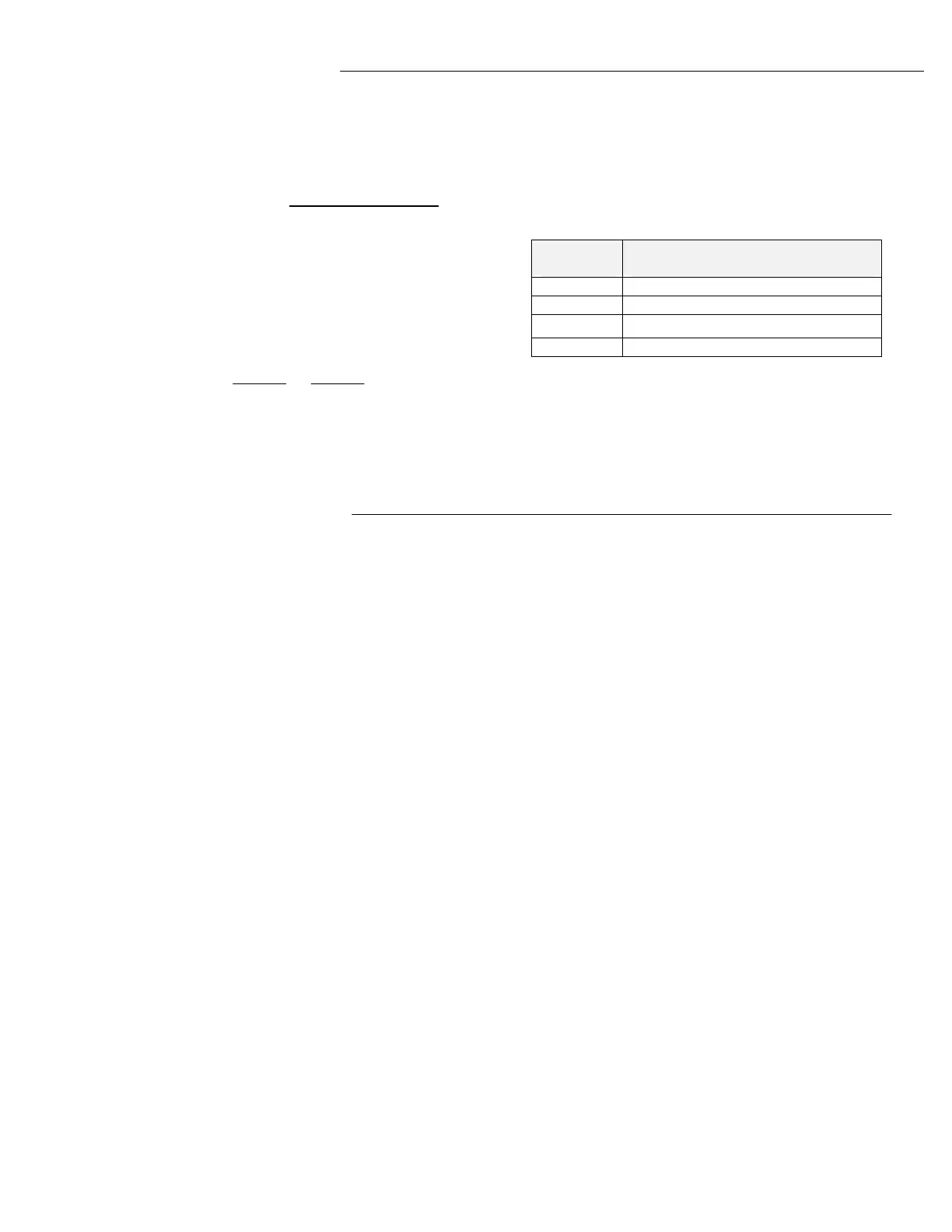
LOW VOLTAGE CONTROL WIRING
Control System Wiring: For commercial equipment the
following table lists the minimum size of 24 volt class 2
wire to be used.
Ft. Run From Unit to
Wire Size System Switch or Longest Run
18 A W G Maximum Run 50 Feet
16 A W G Maximum Run 75 Feet
14 A W G Maximum Run 100/125 Feet
12 A W G Maximum Run 150/200 Feet
Note: Wiring – Consult the wiring diagram furnished with
the unit. These units are custom designed for each
application.
The wiring diagrams in this publication are furnished only
as a guide to the installing contractor. The unit wiring
diagram is located inside the control panel of each unit.
SEQUENCES OF OPERATION
Temperature Controls: The Ambient Compressor
Thermostat controls compressor on/off operation. The
use of space or duct mounted sensors to control the
compressor will produce unpredictable results. On
systems with optional Hot Gas Reheat a discharge air
thermostat is mounted in the air handler. A
temperature/humidity sensor located in the conditioned
space may be used in conjunction with the control for
Hot Gas Reheat. A remote system switch such as a time
clock or interlock may be used to energized the controls.
Mechanical Cooling
The evaporator blower starts when the system switch is
closed. When the outdoor temperature rises above the
set point of the adjustable outdoor thermostat, the
compressor is active until the thermostat is satisfied. The
leaving air temperature will be maintained by hot gas
bypass and/or unloading the compressor. This is
accomplished through suction-pressure sensing, thus
tracking the outside air temperature variations.
When the outdoor temperature falls below the set point
of the adjustable outdoor thermostat (normally 56°F), the
compressor is deactivated.
Condenser Head Pressure Control
VARISPEED fan motor and control is standard with
all reheat options because units operating in low ambient
temperature require a control system to maintain stable
head pressure. Head pressure control is accomplished
with one or two variable speed condenser fan drives. A
pressure sensing control modulates the condenser fan
speed as required to maintain head pressure between
320 psig and 430 psig.
The Varispeed fan motor has been designed and tested
to withstand the high temperatures incurred during
variable speed operation DO NOT SUBSTITUTE.
Single fan models are equipped with one variable speed
motor and control.
Dual fan models may be are equipped with one single
phase variable speed motor and one 3 phase motor.
Four fan models may be equipped with one variable
speed motor and three 3 phase motors.
This pressure sensing system consists of a variable
speed motor driven fan and a constant speed motor
driven fan. Both are controlled from refrigerant pressure
rather than ambient temperature, reflecting actual
operating conditions in the machine.
At low ambient, the variable speed fan operates,
increasing in speed until maximum RPM is achieved at
or around 45°F (±2) ambient. An adjustable pressure
switch operates the constant speed three-phase fan set
to energize the motor at 400 psig and de-energize at 295
psig. In the ambient temperature span of approximately
50°F to 53°F, the variable speed fan will ramp between
maximum and minimum speed while the constant speed
fan cycles. The start-stop cycle varies from 45 seconds
to 22 minutes during this period.
At 53°F (±2), both fans are operating, the variable speed at
minimum RPM and the constant speed at full RPM. As the
ambient continues to rise, the variable speed motor increases
to full speed and remains there.
 Loading...