Do you have a question about the Addison DCA Series and is the answer not in the manual?
Critical safety guidelines before installing and using the air conditioner.
Operational failure warnings and responsibility for safeguards.
Explains DANGER, WARNING, and CAUTION signal words and their application.
Illustrates product labels with color explanations and hazard warnings.
Warning regarding HFC-(R410A) refrigerant and U.S. Clean Air Act requirements.
Specifies clearances and placement considerations for unit installation.
Emphasizes adherence to local codes, ordinances, and installation procedures.
Details requirements for roof curb installation and checking for protrusions.
Procedures for rigging, ductwork, and condensate drainage.
Instructions for power wiring, control wiring, and proper grounding of the unit.
Method for calculating and checking phase voltage unbalance percentage.
Describes compressor operation and VARISPEED fan control.
Details the components and operation of the factory installed hot gas reheat circuit.
Describes the subcooling coil added for humidity control and efficiency.
Explains the application of Reheat Plus for 100% OA systems and efficiency gains.
Details the use of hot gas reheat for humidity control in conditioned spaces.
Describes hot gas bypass, solenoid valves, and refrigerant flow control.
Outlines control methods using thermostats, humidistats, and DDC.
Step-by-step procedure to check blower rotation and electrical phasing.
Critical warnings regarding electrical shock, fire, explosion, and moving parts.
Comprehensive list of checks before unit start-up, including location, wiring, and filters.
Procedures for setting up the unit, charging refrigerant, and adjusting bypass valve.
Procedures for cleaning filters, checking belts, drains, bearings, and cabinet finish.
Checking for loose parts and understanding weep holes for drainage.
Detailed steps for isolating, removing, and installing a compressor.
Information on how to report shortages or damaged parts and order replacements.
Schematic for typical 208/230 volt, single-phase, 60 Hz wiring.
Schematic for typical 208/230 volt, three-phase, 60 Hz wiring.
Schematic for typical 460 volt, three-phase, 60 Hz wiring.
Schematic for typical 380/415 volt, three-phase, 50 Hz wiring.
Explanations of abbreviations, symbols, and important wiring notes.
Essential safety rules for working near belt drives, including power off.
Step-by-step guide to adjusting the variable speed pulley for desired blower speed.
Procedures for checking pulley alignment and setting belt tension.
Diagnosing problems when the compressor fails to start or cuts out.
Troubleshooting thermal overload cutouts, oil failure controls, and noisy compressors.
Identifying causes for noisy operation related to blowers and system noise.
Diagnosing problems related to abnormal suction or discharge pressures.
Troubleshooting compressor short cycling and low head pressure conditions.
Diagnosing issues with long running cycles or incorrect supply air temperatures.
Troubleshooting problems with liquid lines, suction lines, and frosting.
Identifying causes for the blower motor failing to run or tripping overload.
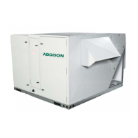
| Brand | Addison |
|---|---|
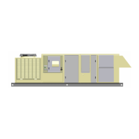
| Model | DCA Series |
| Category | Air Conditioner |
| Language | English |