4
INSTALLATION (CONT’D)
Curb Installation, Protrusions
Proper installation for the TRS series requires that the roof mounting of the curb be firmly and permanently attached to the
roof structure. Check for adequate fastening method prior to setting rooftop unit on curb.
Inspect curb to insure that none of the utility services (electric, gas, drain lines) routed through the curb protrude above
the curb. Being a fully welded solid bottom curb, duct connections can be made before unit is set on curb. Duct openings
are to be sized and cut by the installing contractor in the solid curb.
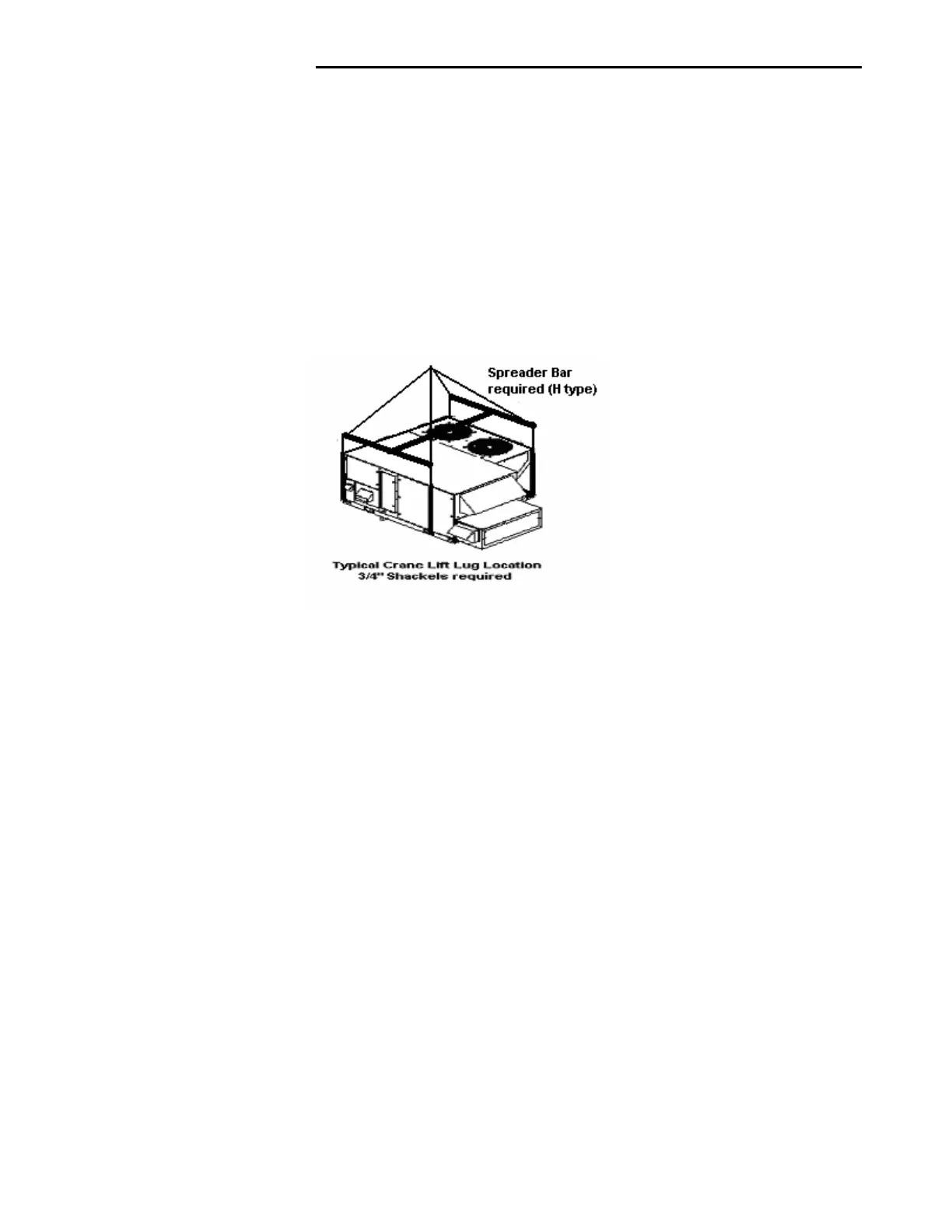
Rigging
WARNING: Be sure that the crane and lift material (bars, cable, chain), (or other lifting device) capacity is adequate for
the unit weight. See Addison Products Company specification literature for unit weights. The total unit weight calculated
must include all appropriate options for your unit. Certain options can add significant weight to a unit.
Spreader bars keep the lift cables from damaging the cabinet once the unit has been lifted, these bars will be required in
all instances. Keep the tension equal, improper lift tension can damage wiring, refrigeration lines and the water tight
integrity of the cabinet as well as sheet metal damage to the unit cabinet.
Figure 1
Lower unit carefully onto roof mounting curb or mounting rails or ground level slab. While rigging unit, center of gravity will
cause condenser end to be lower than supply/return air end. Bring condenser end of unit into alignment with curb. With
condenser end of unit resting on curb member and using curb as fulcrum, lower front end of unit until entire unit is seated
on curb.
Rigging Removal
Remove spreader bars, lifting cables and other rigging equipment. Use caution not to dent scratch or otherwise damage
cabinet or intake and exhaust hoods.
CAUTION: Do not allow crane hooks and spreader bars to rest on roof of the unit.
ELECTRICAL
Wiring Connections
Power wiring should be connected to the main power terminal block located within the unit main control section. Power
wiring connections on units with factory disconnects should be made at the line side of the disconnect switch.
Low voltage wiring connections are made to the remote mounted controller or time clock.
DO NOT TAMPER WITH FACTORY WIRING
Contact your local representative or the factory if assistance is required. The internal power and control wiring of these
units is factory installed and each unit is thoroughly tested prior to shipment.
Independent Power Source
It is recommended that an independent 115-volt power source be brought to the vicinity of the rooftop unit for portable
lights and tools used by the service mechanic.
Main Power Wiring
The units are factory wired for the voltage shown on the nameplate.
Main power wiring should be sized for the minimum wire ampacity shown on the nameplate.
An external weather-tight disconnect switch properly sized for the unit total load is required for each unit. Disconnect must
be installed in accordance with Local and/or National Electric Codes.
 Loading...