page 50 IRIS-4 Technical Reference Manual.docx 12/01/2023
8 Installation for VdS 2463 Compliance
8.1 Introduction
AddSecure IRIS-4 alarm over IP terminals have been tested and certified by VdS in Germany to comply with
the VdS2463 standard, “Alarm Transmission for alarm signals (ATE)” and have been given a “G” approval
rating.
The IRIS-4 models certified to VdS2463 and for which this guide is applicable include IRIS-4 400, 420 and 440.
For compliance with this standard, the installer must set the terminal to operate in one of:
VdS Intruder mode
VdS Fire mode.
8.2 Installation
AddSecure provides a special VdS compliant enclosure and wiring kit that includes:
Mounting points for the terminal.
A tamper proof enclosure.
A tamper detection switch.
Termination connector blocks and sense resistors for the connection and monitoring of the inputs from the
alarm system.
An external relay for fire applications.
Cable ties for strain relief.
The IRIS-4 terminal must be used with this enclosure and powered from the Intruder Alarm System Alarm
Control and Indicating Equipment (IAS-CIE). This additional power consumption must be considered when
calculating the standby duration.
Note: If these conditions are not followed, then the installation will not comply with VdS2463.
For VdS 2463 compliant installations, the terminal must be set to use only the pin inputs. The dial capture (2
wires) interface cannot be used as it is not compatible with the VdS terminal protocols.
The terminal can be set to operate in conformance to VdS 2463 in either VdS Intruder or VdS Fire mode.
Follow this procedure to set the pin inputs for these modes:
1 Follow the instructions in chapter 4 “Basic Setup” and chapter 5
“Configuring the terminal” to configure the terminal.
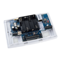
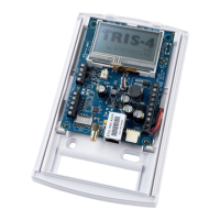
2 Go to Settings «Extra Features» menu.
3 Tick «VdS 2463 Fire» or «VdS 2463 Intruder» as required.
4 Go to Settings Pin Inputs.
5 Enter the appropriate messages and configurations for the pins to
be used, see section 6.13 “Pin inputs”.
6 Enable tamper detection on all used input pins, except pin 1, to
enable monitoring of the inputs with the end of line resistors (see
section 6.13).
7 Disable unused pins, then click «Back».
Note: To conform to the VdS standard, shielded cables shall not be used for interconnection with the
Intruder IAS-CIE.