ADJ Products, LLC - www.adj.com - Element QA User Manual Page 10
ADJ Products, LLC - www.adj.com - Element QA User Manual Page 11
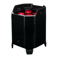
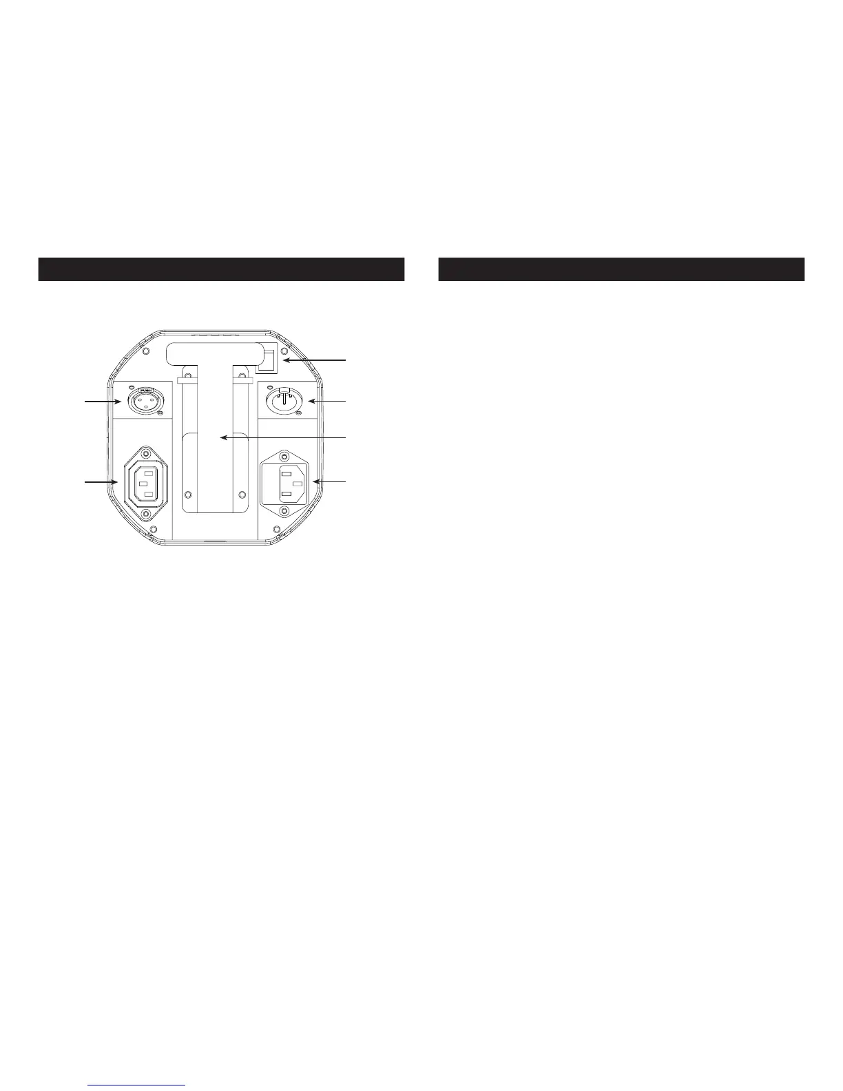
Element QA Layout Diagram Element QA DMX Control
DMX Connections and Power Connections: All connections are
located underneath the unit. You will nd all connections and
other features pointed out below.
1
5
6
4
3
2
1. Battery On/O Switch: This switch is used to activate the battery
power. You must also activate the LOAD function. See page
23 “Load Setting” to activate.
2. 3-Pin DMX In: This input is used to send a DMX signal to a con-
nected unit for master-slave set up.
3. Kickstand: This kickstand is used to angle the unit to various
degrees. There are 3 dierent degree levels. Note: Be very
cautious at the degree in which you angle the unit at, due to
the fact that it could fall over.
4. Power Input & Fuse Holder: This input is used to connect the
included I.E.C. power cord. After connecting the power
cord, plug the other end into a matching power source.
Located inside the power socket is the fuse housing. See
page 37 for fuse replacement.
5. Power Output: This connection is used to receive a incoming
power source from another unit.
6. 3-Pin DMX Out: This output is used to send a DMX signal to a con-
nected unit for master-slave control.
DMX Mode:
Operating through a DMX controller gives the user the freedom to
create their own programs tailored to their own individual needs.
This function also allows you to use your fixtures as spot lights. The
Element QA has 5 DMX modes: 4 channel mode, 5 channel mode,
6 channel mode, 9 channel mode, and 10 channel mode. See pages
12-21 for each mode’s DMX traits.
1. This function will allow you to control each individual fixture’s
traits with a standard DMX 512 controller.
2. To run your fixture in DMX mode press the MODE button until
“d.XXX” is displayed. “XXX” represents the current displayed DMX
address. Use the UP or DOWN buttons to select your desired
DMX address, then press the SETUP button to select your DMX
Channel mode.
3. Use the UP or DOWN buttons to scroll through the DMX Channel
modes. The Channel modes are listed below:
• To run the 4 Channel Mode, press the MODE button until “Ch04”
is displayed. This is the 4 Channel DMX Mode.
• To run the 5 Channel Mode, press the MODE button until “Ch05”
is displayed. This is the 5 Channel DMX Mode.
• To run the 6 Channel Mode, press the MODE button until “Ch06”
is displayed. This is the 6 Channel DMX Mode.
• To run the 9 Channel Mode, press the MODE button until “Ch09”
is displayed. This is the 9 Channel DMX Mode.
• To run the 10 Channel Mode, press the MODE button until
“Ch010” is displayed. This is the 10 Channel DMX Mode.
4. Please see pages 11-22 for DMX values and traits.
5. After you have chosen your desired DMX Channel mode plug in
the fixture via the XLR connections to any standard DMX control-
ler.