4 61287802F1-13F
2. Route the fiber in the fiber tray and terminate it at the
bulkhead connector.
3. Connect a fiber jumper from the bulkhead connector to the
SC/APC connector at the bottom of the ONT (refer to Figure
7).
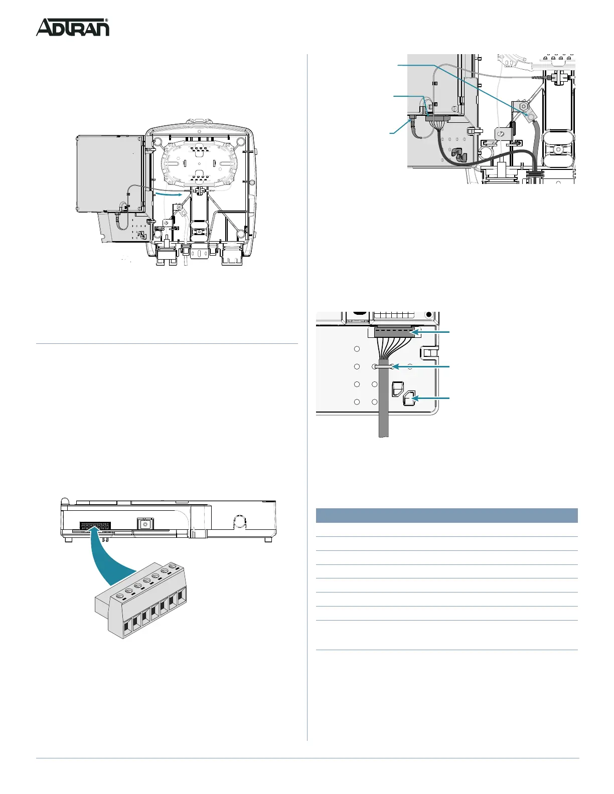
Figure 7. Fiber jumper to the ONT
4. Route the fiber jumper so that when the ONT is closed, the
fiber is not pinched.
Connect Power/Alarm
Before making any power connections to this equipment, verify the
power is off (fuse removed/breaker tripped). This equipment should
only be operated from the type of certified/listed power supply
supplied by the manufacturer with the equipment.
The ONT is supplied with a 7-pin Power/Alarm Connector. Refer to
the following steps and the two figures below to connect Power/
Alarms to the ONT.
1. Remove the Power/Alarm Connector (shown in Figure 8) from
the accessory bag.
Figure 8. Power/Alarm Connector
2. Route the Power/Alarm wire through the port as shown in
Figure 9.
2345671
Power/Alarm Connector
Pin 1
Pin 7
Figure 9. Power/Alarm Connection and Routing
3. Terminate the 2 power leads (Pins 6 and 7), and the five
Uninterruptible Power Supply (UPS) leads (see the pinout
table).
4. Connect the Power/Alarm connector to the bottom of the ONT
(refer to Figure 8).
5. Tie wrap and route these wires as shown in Figure 10. This
will prevent the connector from coming loose when the ONT is
closed.
Figure 10. Power/Alarm Connector Installed
The following table provides a pinout of the Power/Alarm connector.
Install a Local Power Source
The ONT must be powered by a UL Listed Power Supply suitable
for the application (rated 12 VDC, 1.25 A minimum) with an LPS
output. Installation of the Local Power Source will be dictated by on-
site conditions and local telephone company practices.
PIN Description
1
Low Battery
2
Battery Missing
3
Replace Battery
4 On Battery
5 Signal Return
6 12 V Return
7
+12 VDC
Fiber Connection
Ground Connection
Power Connection
7
S
O
R
B
L
1
+
654321
Tie Wrap Wires as shown
Note:
Even though there are brackets
to position the Power / Alarm
Connector wires, their use is
not recommended. Use of
these brackets can “bind” the
wires when the ONT is closed.
Power / Alarm Connector
ule
 Loading...