Physical Descriptions NetVanta 3200/3300/3400 Series
18 Copyright © 2012 ADTRAN, Inc. 61200860L1-34AB
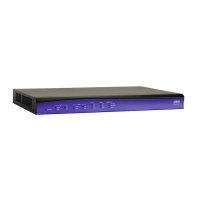
NetVanta 3200 Front Panel Design
The NetVanta 3200 front panel is shown below. Front panel LED descriptions are given in Table 1 on page 40.
Figure 1. NetVanta 3200 Front Panel Layout
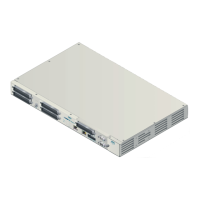
NetVanta 3200 Rear Panel Design
The NetVanta 3200 rear panel is shown below. Appendix A on page 85 provides pinouts.
Figure 2. NetVanta 3200 Rear Panel Layout
NetVanta 3200 Rear Panel Interfaces and LEDs
SLOT 1 NET/DBU Option Slot
The SLOT 1 NET/DBU option slot supports various plug-in NIMs. These option modules are described
in the section Option Modules on page 41.
10/100Base-T Ethernet Interface and Activity LEDs
The Ethernet port (ETH 0/1) is an RJ-45 connector with LEDs. The amber activity LED flashes when
data traffic is being sent or received on the Ethernet port. The green link LED is on when the router has
a good connection to the LAN. The Ethernet port provides the following:
• 10Base-T or 100Base-T with a single connector
• Auto-negotiation
•CSMA/CD
• IEEE 802.3 compatibility
CONSOLE Interface
The CONSOLE interface is an EIA-232 serial port (DCE) that provides for local management and
configuration (via a DB-9 female connector)

 Loading...