2 61287736G3-22B
Connecting POTS
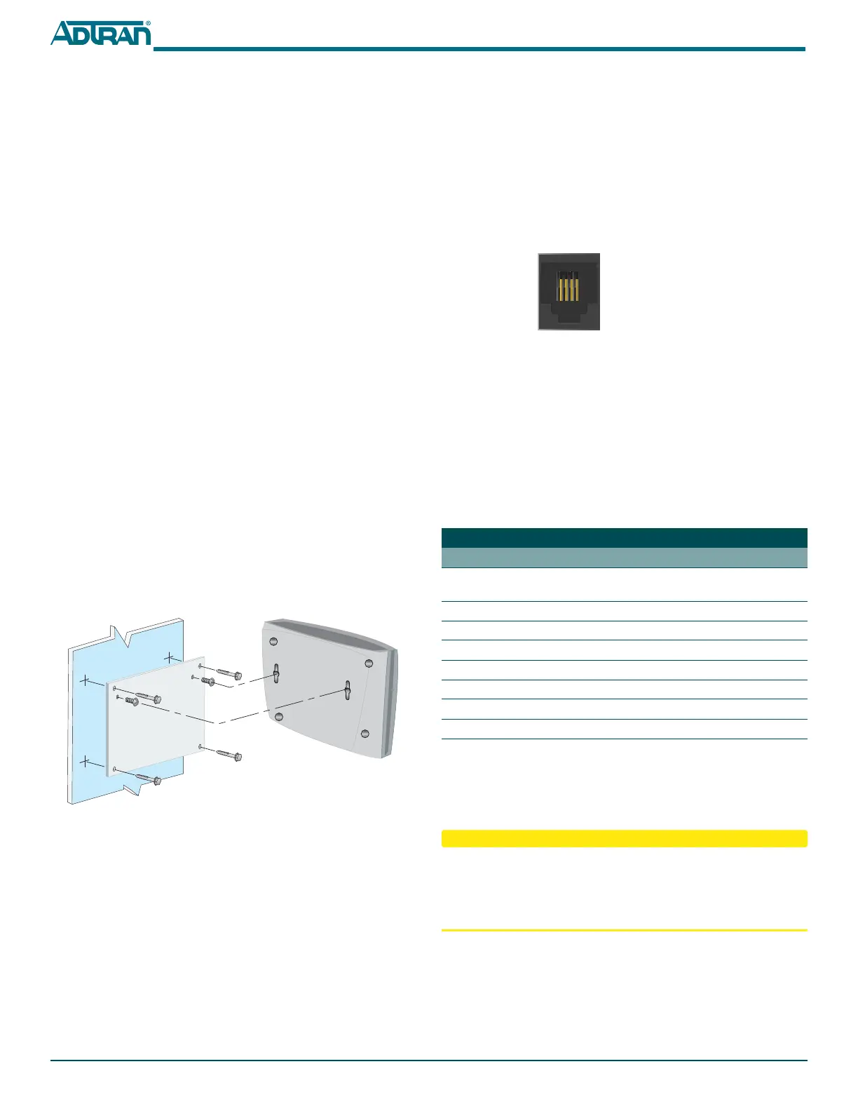
If POTS cables are not available, refer to Figure 2 and the following
procedure to create the POTS cables:
1. Trim the insulation for the subscriber POTS cables.
2. Refer to the illustration below and connect the twisted pair Tip
(green) and Ring (Red) to the RJ-11 connector using an RJ-11
crimper.
3. Insert the RJ-11 connector in the appropriate POTS 1 or POTS 2
jack.
Figure 2. POTS RJ-II Connector
Connecting Ethernet
The SFU ONT supports four 1 Gigabit (10/100/1000Base-T) connec-
tions (
LAN 1 to LAN 4).
If Ethernet cables are not available, use the following procedure and
table to create the Ethernet cables:
1. Trim the insulation for the subscriber Ethernet cable.
2. Connect the wires per the following table using an RJ-45
Crimper.
3. Insert the CAT 6 rated cable in the appropriate
LAN 1 through
LAN 4 ports.
Installing Fiber
LASER RADIATION
1500 nm to 1600 nm
Do not view directly with optical instruments.
This product contains a Class 1M Laser module that complies with 21
CFR 1040.10 and 1040.11 and IEC 60825-1 and -2.
Fiber is installed in an SC connecter located behind a removable
protector panel on the right-rear of the SFU ONT. Refer to Figure 3
when installing fiber:
1. Remove the phillips-head screw from the right side of the fiber
protector panel.
2. Slide the protector cover back to expose the SC connector.
Ethernet RJ-45 Pin-out
Pin Name Description Color Code
1 TRD0+ Transmit/Receive Positive White/
Orange
2 TRD0- Transmit/Receive Negative Orange
3 TRD1+ Transmit/Receive Positive White/Green
4 TRD2+ Transmit/Receive Positive Blue
5 TRD2- Transmit/Receive Negative White/Blue
6 TRD1- Transmit/Receive Negative Green
7 TRD3+ Transmit/Receive Positive White/Brown
8 TRD3- Transmit/Receive Negative Brown
1 2 3 4
1 = Not Connected
2 = Tip
3 = Ring
4 = Not connected
Installation consists of positioning the SFU ONT either on a desktop
or wall mount, connecting POTS, Ethernet and Fiber, and connecting
power.
Required tools
Standard technician tools and those listed below are required for
installing the SFU ONT:
■ Carpenter’s level
■ 3/32 inch screw driver for connecting SFU ONT power
■ RJ-45/RJ-11 crimper
■ A telephony/data communication test set
■ PON power meter with wavelength filtering
■ Fiberscope or videoscope
■ Two #8 Pan Head screws (1 inch or greater in length)
■ Assorted tie wraps for securing cabling and wiring
For fiber optic connections, the following are required:
■ Fiber Optical Fusion Splice Tools
■ ODC Fiber cleaning tool
■ SC Fiber connector
Desk Top Installation
The SFU ONT can sit on a desktop or be wall mounted. With a desk
mount, ensure the SFU ONT is not located in direct sunlight and is
not located next to any thermal obstructions.
Wall Mount Installation
The SFU ONT can be wall mounted.
To wall mount the SFU ONT, reference Figure 1 and complete the
following steps:
1. Decide on a location for the SFU ONT. Mount below eye-level
so the LEDs are visible.
Figure 1. Wall Mount SFU ONT
2. Attach a 1/4 inch mounting board (typically plywood) to the
wall. If the wall is drywall construction, ensure the mounting
board is supported by the wall studs.
3. Install two #8 Pan Head screws (1 inch or greater in length)
using the key holes on the back of the SFU ONT as location
markers. Leave approximately 1/4 inch protruding from the
mounting surface.
4. Slide the SFU ONT over the Pan Head screws and exert a small
amount of downward pressure to ensure that the top of the
slots are resting on the shafts of the Pan Head screws.